
 0
 EN
 English
 عربى
 Español
 русский
If you need any help, please feel free to contact us
Home / Author / Ding Yuchun — Overseas After-Sales Support Engineer / Small-Pipe Clamp-On Ultrasonic Flow Measurement for Industrial Water and Energy Systems
Small-Pipe Clamp-On Ultrasonic Flow Measurement for Industrial Water and Energy Systems
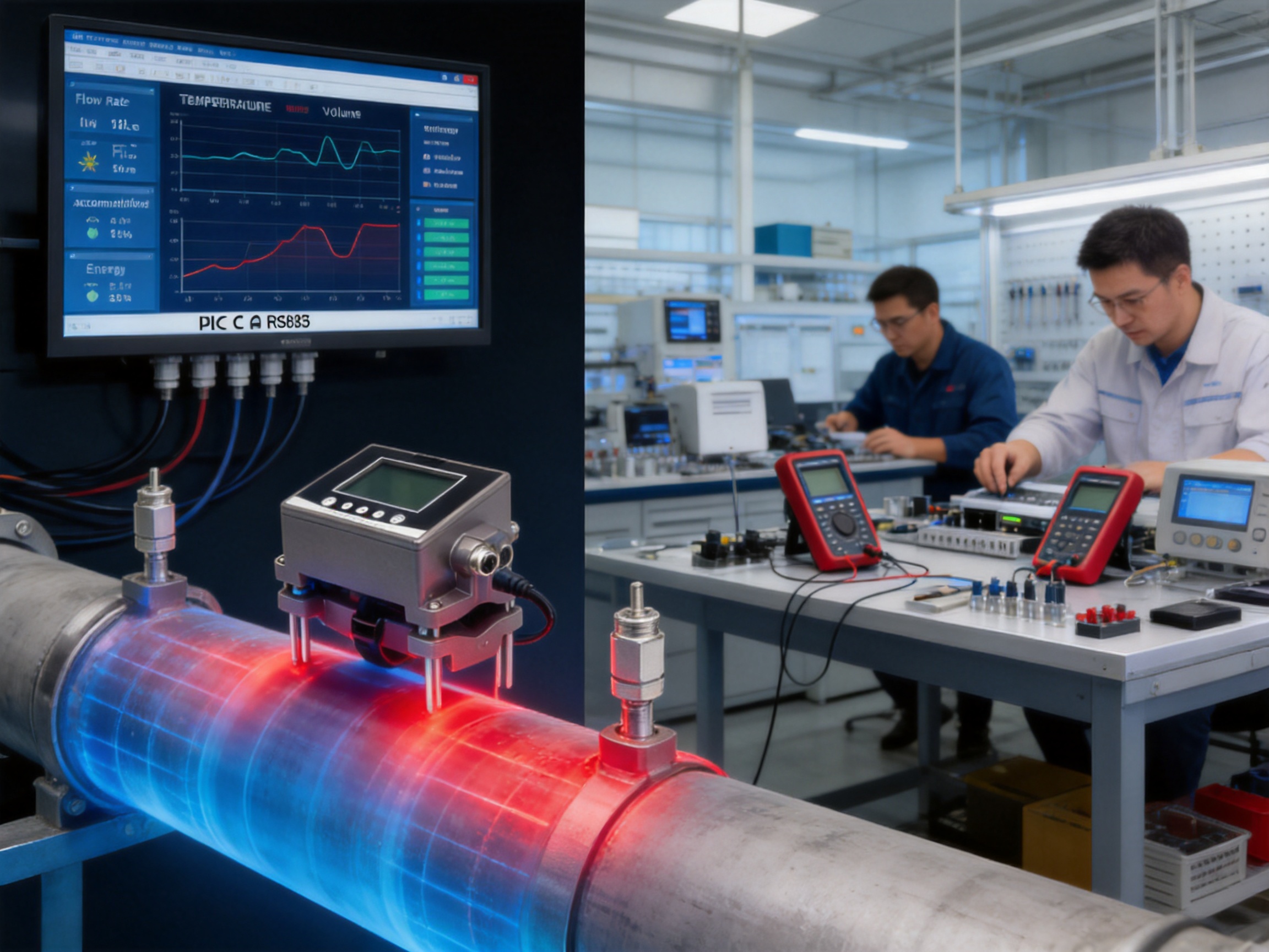
Accurate flow measurement is essential for water distribution, heating and cooling systems, industrial utilities, equipment skids, process monitoring, and automation. However, installing a flow meter in an existing pipeline is not always simple. Cutting the pipe, draining the system, welding flanges, interrupting production, and recalibrating the process can create substantial cost and operational risk. These challenges are particularly significant when the pipeline is small, access is limited, or continuous operation must be maintained.
The VNFT211 Clamp-On Ultrasonic Flow Meter provides a practical solution for these conditions. Designed for pipe sizes from DN15 to DN65, the instrument measures the flow of water and other clean, single-phase liquids from outside the pipe. Its external transducers are clamped to the pipe wall, allowing the measurement system to operate without direct contact with the liquid, without cutting the pipeline, and without creating an obstruction inside the flow path.
Based on the transit-time ultrasonic principle, the VNFT211 calculates flow velocity by comparing the travel time of ultrasonic signals moving upstream and downstream through the pipe wall and liquid. The difference between these two transit times is proportional to the velocity of the flowing liquid. Combined with the programmed internal pipe diameter and installation parameters, the meter calculates instantaneous flow rate and accumulated volume.
This design gives the VNFT211 several advantages over intrusive flow meters and many conventional retrofit solutions. It avoids pressure loss, minimizes contamination risk, reduces installation time, and supports measurement in operating systems. Its compact small-pipe configuration, LCD display, industrial outputs, energy-metering option, protective functions, and flexible installation make it suitable for both permanent and temporary measurement tasks.
Product Overview
The VNFT211 is a small-diameter clamp-on ultrasonic flow meter developed for industrial and building-service applications. It is intended primarily for clean water and other single-phase liquids without significant solid particles, gas pockets, or impurities. The meter uses two external ultrasonic transducers positioned on the outside surface of the pipe. Depending on the pipe material and installation conditions, the transducers may be mounted in a selected spacing and orientation that allows the ultrasonic signal to pass through the pipe wall and liquid.
Unlike an electromagnetic flow meter, the VNFT211 does not require electrodes in contact with the liquid. Unlike a turbine meter, it does not place a rotating element in the flow path. Unlike a mechanical insertion meter, it does not require a penetration point in the pipeline. Unlike many inline meters, it can usually be installed while the process remains filled and operating.
The device is designed for DN15–DN65 pipelines made from metal or rigid plastics such as PVC, PP, and PVDF. This range covers many branch lines, equipment connections, laboratory systems, packaged skids, utility circuits, and building-service pipelines. The meter is especially valuable where the pipe diameter is too small for a large portable ultrasonic system but where a permanent inline meter would require disproportionate installation work.
The standard measurement accuracy is ±2%, with accuracy of up to ±1% possible after calibration under suitable installation and operating conditions. The operating liquid temperature range is 0 to 115 °C, provided that the pipe surface is not frozen and the transducer mounting conditions remain within the specified limits. The flow meter operates from a 10–24 VDC power supply and consumes less than 3 W.
| Parameter | Specification | Practical Significance |
|---|---|---|
| Measurement principle | Transit-time ultrasonic measurement | Non-intrusive velocity and flow measurement |
| Pipe size | DN15–DN65 | Suitable for small-diameter industrial and utility pipelines |
| Pipe material | Metal, PVC, PP, PVDF, and other rigid plastics | Supports common industrial pipe systems |
| Liquid type | Water and other clean, single-phase liquids | Suitable for water, chilled water, heating water, and utility liquids |
| Liquid temperature | 0–115 °C | Supports normal water systems and many heating applications |
| Accuracy | ±2%; up to ±1% after calibration | Supports monitoring, balancing, verification, and control |
| Display | 256 × 128 LCD | Provides direct local access to flow and status information |
| Power supply | 10–24 VDC | Compatible with common industrial control power systems |
| Power consumption | Less than 3 W | Suitable for continuous operation and distributed installations |
| Analog output | 4–20 mA | Supports PLC, DCS, and conventional instrumentation systems |
| Communication | Modbus RS485 | Enables digital data acquisition and remote supervision |
| Optional outputs | Pulse output and relay alarm | Supports totalization, alarms, and auxiliary control functions |
| Enclosure | IP65 | Protects against dust and water jets in suitable industrial environments |
| Response time | 0.5–60 seconds, adjustable | Allows selection of fast response or smoother indication |
How Transit-Time Ultrasonic Measurement Works
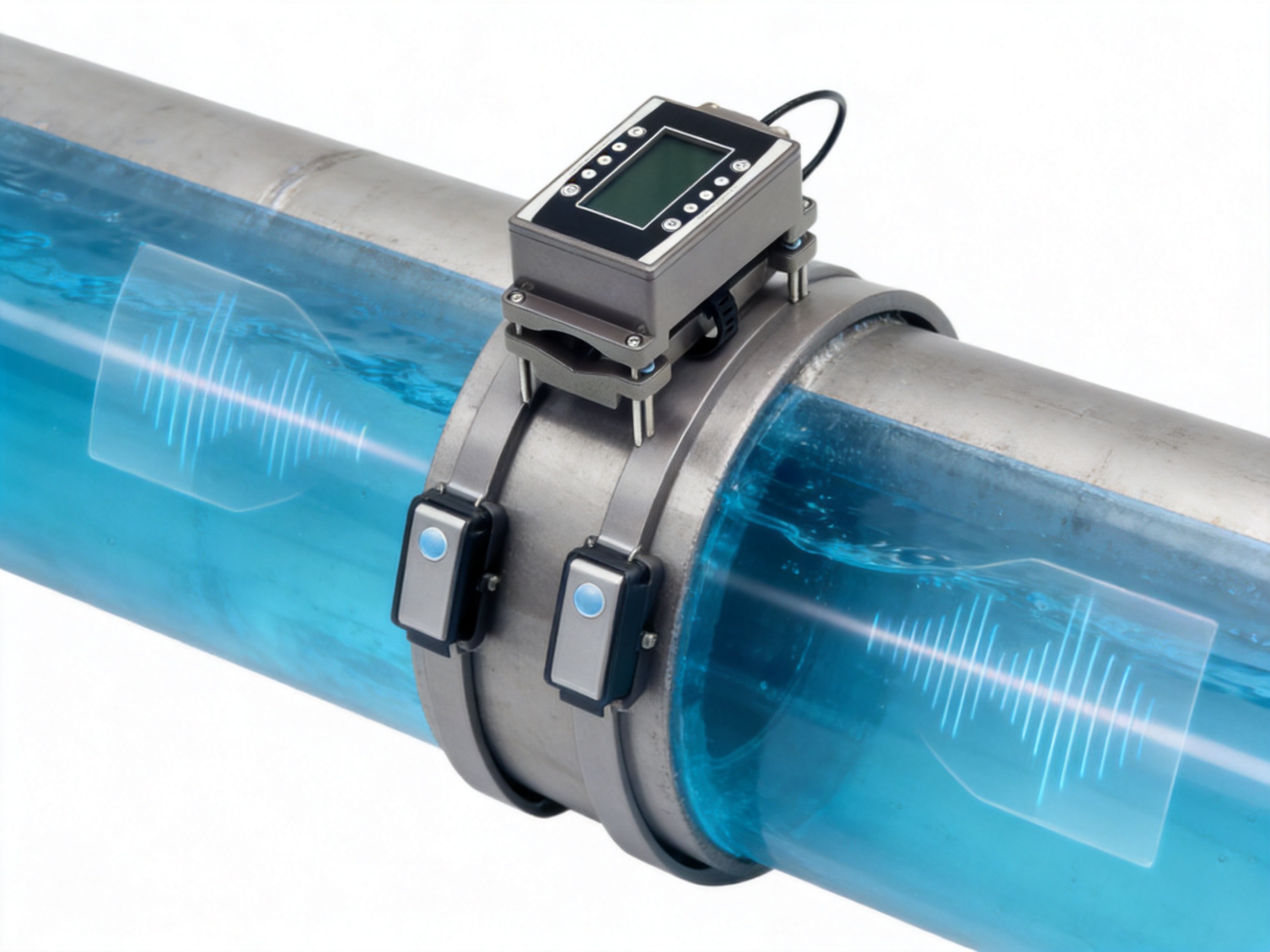
The VNFT211 uses the transit-time method. Two ultrasonic transducers are installed on the external surface of the pipe. One transducer sends an acoustic signal in the direction of liquid flow, while the other sends a signal against the direction of flow. The instrument measures the time required for the signals to travel between the transducers.
When the liquid is stationary, the upstream and downstream travel times are substantially related to the same acoustic path and fluid conditions. When the liquid flows, the signal moving in the direction of flow travels slightly faster than the signal moving against the flow. The resulting time difference is very small, but it can be measured electronically. The meter uses this difference to calculate the average flow velocity along the ultrasonic path.
The flow velocity is then combined with the internal cross-sectional area of the pipe. After the pipe size and relevant installation parameters are entered, the system determines the volumetric flow rate. The meter can also accumulate the measured flow to provide total volume information over time.
Because the transducers are outside the pipe, the measurement method does not require a wetted sensor, internal rotor, or electrode. The pipe remains mechanically intact and the liquid follows the original hydraulic path. This is especially important in systems where pressure loss, contamination, hygienic concerns, or process interruption must be avoided.
Reliable ultrasonic measurement depends on several installation factors. The liquid should be reasonably homogeneous and free from excessive entrained air. The pipe should be full at the measuring point, and the selected location should provide stable flow conditions. Straight pipe sections upstream and downstream are preferred because elbows, valves, pumps, tees, and reducers can disturb the velocity profile. Correct transducer spacing, firm mounting, clean pipe surfaces, and accurate parameter entry are also important.
Non-Intrusive Installation Without Pipeline Modification
The most direct advantage of the VNFT211 is its clamp-on configuration. Conventional inline flow meters generally require the pipeline to be opened, cut, drained, or modified. Depending on the installation, this may involve welding, flange alignment, gasket replacement, pressure testing, cleaning, and recommissioning. Each step increases labor requirements and extends downtime.
The VNFT211 avoids these activities in many retrofit applications. The external transducers are placed on the existing pipe and secured with the appropriate mounting arrangement. There is no need to remove a section of pipe or insert a probe into the liquid. The system can therefore be installed on operating pipelines when site conditions, safety procedures, and the application permit.
This feature is valuable for water supply networks, HVAC branches, industrial cooling circuits, process utility lines, and temporary diagnostic projects. A facility can obtain flow data without redesigning the piping system. Maintenance teams can verify actual flow rates without taking equipment out of service. Engineering contractors can perform commissioning checks without installing a permanent meter at every test point.
Non-intrusive measurement also avoids the pressure loss associated with internal restrictions. A turbine rotor, orifice plate, partially closed valve, or intrusive probe may create additional resistance. The VNFT211 does not introduce a new obstruction into the pipe, helping preserve the existing hydraulic performance of the system.
Because the sensor does not touch the process liquid, there is no wetted electrode or rotating part to corrode, foul, wear, or contaminate the medium. This does not make the system suitable for every liquid, but it reduces the number of liquid-compatibility issues normally associated with wetted instruments. The external installation is also useful when the liquid composition is changing or when a clean process must not be exposed to instrument materials.
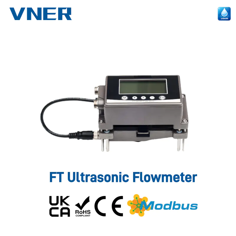
VNFT Clamp-On Ultrasonic Flow Meter
Advantages for Small-Diameter Pipe Measurement
Small pipes are common in building services, equipment packages, laboratory utilities, pilot plants, and branch distribution systems. They can also be difficult to instrument economically. A conventional inline meter may occupy a large amount of straight-run space compared with the pipe itself. Installation may require reducers, additional supports, isolation valves, or a bypass line. For a small branch with modest flow, these additions may be difficult to justify.
The VNFT211 is specifically designed for DN15–DN65 pipe sizes. This focus gives it a practical role in applications that are not well served by general-purpose large-pipe ultrasonic instruments. Its compact sensor arrangement is intended for small pipe geometry, while its control electronics provide local display and industrial communication functions normally expected in larger process instruments.
Small-diameter applications often involve compact equipment layouts. There may be limited clearance around a chiller connection, pump skid, heat exchanger, laboratory test loop, or machine utility line. A clamp-on meter can be positioned on the accessible exterior of the pipe without adding a long inline body. This simplifies installation in crowded mechanical rooms and packaged systems.
The device is compatible with metal pipes and rigid plastic pipes, including PVC, PP, and PVDF. This material flexibility is useful because industrial facilities often combine carbon steel, stainless steel, copper, and engineered plastic piping in the same water or utility network. Proper acoustic coupling and installation preparation remain important, but the meter is not limited to a single pipe construction.
Performance Compared with Conventional Flow Meter Technologies
Comparison with Mechanical Turbine Meters
A turbine meter uses a rotating element positioned in the flow path. It can provide useful measurement performance, but the rotor introduces moving parts that may wear or become affected by suspended matter. The meter may also require strainers, isolation valves, and a suitable straight-run arrangement. Maintenance can require process shutdown and removal of the instrument.
The VNFT211 has no internal rotor. Its external transducers do not obstruct the flow, and there are no bearings or rotating blades in contact with the liquid. This makes the clamp-on meter attractive for retrofit measurement, temporary verification, and systems where maintenance access is limited. The trade-off is that ultrasonic measurement requires appropriate acoustic conditions and careful installation, whereas a turbine meter may be more tolerant of certain signal-related issues in a clean, well-controlled mechanical installation.
Comparison with Electromagnetic Flow Meters
Electromagnetic flow meters are widely used for conductive liquids and can offer excellent performance in permanent installations. They normally require a wetted measuring tube, electrodes, a full pipe, and an electrically conductive liquid. Installing an electromagnetic meter in an existing line may require cutting the pipe and adding flanges or threaded connections.
The VNFT211 does not require liquid conductivity and does not place electrodes in the process. It can measure water through the existing pipe wall and can be installed without creating a new wetted section. This gives it a strong advantage for retrofit projects and for applications in which the pipe must remain unchanged. However, the liquid and pipe conditions must support ultrasonic signal transmission, so application assessment remains necessary.
Comparison with Vortex and Differential-Pressure Devices
Vortex meters and differential-pressure meters may require internal flow disturbances or pressure-sensing connections. These devices can be reliable in appropriate applications, but they often require more installation space, suitable straight lengths, and permanent mechanical integration. Differential-pressure devices also create a pressure drop and may require impulse lines or additional transmitters.
The VNFT211 is designed to minimize mechanical intervention. It has no primary restriction, does not depend on a pressure tap, and can be added to an operating pipe from the outside. These characteristics make it useful when the main objective is to obtain flow data quickly without changing the process hydraulics.
Comparison with Portable Clamp-On Instruments
Portable ultrasonic meters are useful for surveys and short-term testing, but they may be designed primarily for temporary use and may not provide the same permanent communication, alarm, and energy-monitoring functions required by an automated system. The VNFT211 combines clamp-on installation with fixed industrial outputs, a local LCD, adjustable response time, long-term data retention, and optional thermal-energy functionality.
As a result, the instrument can serve both as a permanent monitoring meter and as a practical diagnostic tool. A facility may install it permanently on a critical branch or use it for comparative verification, commissioning, and performance audits where a temporary measurement point is required.
| Characteristic | VNFT211 Clamp-On Ultrasonic Meter | Typical Inline Meter |
|---|---|---|
| Pipe modification | Normally not required | Often requires cutting, threading, or flanging |
| Process interruption | Can often be installed while operating | Usually requires shutdown and draining |
| Flow obstruction | None inside the pipe | May include rotor, electrodes, probe, or primary element |
| Wetted components | None | Commonly required |
| Pressure loss | Negligible added loss | May introduce measurable loss |
| Maintenance access | External sensor and electronics access | May require line isolation and removal |
| Small-pipe suitability | Designed for DN15–DN65 | Depends on meter design and installation space |
| Temporary verification | Well suited | Generally less convenient |
| Control integration | 4–20 mA, RS485, optional pulse and relay | Depends on selected transmitter |
| Energy-meter option | Available for cooling and heating applications | Depends on system configuration |
Local Display and Industrial Communication
The VNFT211 includes a 256 × 128 high-resolution LCD. The display provides direct access to flow rate, accumulated flow, status information, and alarm conditions. Local visibility is important during commissioning because technicians can confirm the measurement without immediately connecting a laptop, portable communicator, or control-room workstation.
The display also supports routine operating checks. Maintenance personnel can review flow values in the field, observe whether the instrument is operating normally, and identify alarm or status information at the measuring point. This is particularly useful in mechanical rooms, utility areas, and distributed equipment installations where a central control system may not provide every diagnostic detail.
The standard 4–20 mA output allows the instrument to connect with PLCs, DCS systems, data loggers, building-management systems, and conventional analog input modules. The current signal can be scaled to the required flow range and used for monitoring, control, trending, or alarm logic.
Modbus RS485 communication provides a digital connection for automation and data acquisition. It can support remote reading, centralized supervision, historical analysis, and integration into plant information systems. Optional pulse output can be used for totalized flow or external counters, while relay alarm output can provide a local switching signal for abnormal flow conditions.
This combination of local and remote interfaces gives the meter greater flexibility than a display-only instrument. It can operate as a stand-alone field indicator, a control-system transmitter, a temporary data source, or part of a broader energy-management program.
Optional Cooling and Heating Energy Measurement
The VNFT211 can be configured as an ultrasonic cooling or heating energy meter, commonly called a BTU meter. In this configuration, flow measurement is combined with temperature measurement to estimate thermal energy transferred through a chilled-water or heating-water circuit.
Thermal energy monitoring is important in commercial buildings, industrial facilities, district energy systems, data centers, and process plants. Measuring only flow does not show how much useful heating or cooling energy is being delivered. By combining flow and temperature information, the system can support consumption monitoring, equipment performance assessment, energy allocation, and efficiency analysis.
Typical applications include monitoring chiller inlet and outlet circuits, evaluating heating-system distribution, checking heat-exchanger performance, and allocating energy use among tenants, production areas, or equipment groups. The clamp-on installation approach is especially attractive for existing HVAC systems because it avoids major pipe modification in occupied buildings or operating plants.
Energy measurement should be applied with suitable temperature sensors, correct sensor positioning, and proper configuration of the fluid properties and system arrangement. The accuracy of the overall energy calculation depends on the flow measurement, temperature measurement, sensor matching, installation quality, and operating stability. Even so, the optional energy function provides a practical path from basic flow monitoring to broader utility-management work.
Reliable Operation in Industrial Environments
Industrial instruments are often exposed to vibration, electrical disturbances, temperature changes, humidity, and demanding maintenance conditions. The VNFT211 includes several features intended to support stable operation in these environments.
The factory low-velocity cutoff is set at 0.08 m/s. This function helps prevent the instrument from interpreting very small signal variations or environmental disturbances as meaningful flow. A low-flow cutoff is useful in systems that experience pump cycling, intermittent demand, or near-zero operating conditions. It can make totalized flow data more meaningful by excluding readings below the practical measurement threshold.
The response time is adjustable from 0.5 to 60 seconds. A shorter response time allows the display and output to react quickly to changes, which can be useful during commissioning, control adjustment, or transient analysis. A longer response time smooths rapid fluctuations and may provide a more stable signal for general monitoring. The appropriate setting depends on whether the priority is fast detection or stable indication.
EEPROM-backed data storage provides long-term retention of configured information and relevant operating data. The stated backup period exceeds ten years under appropriate conditions. This helps protect settings during power interruptions and supports long-term equipment operation without relying on continuous external storage.
The IP65 enclosure rating provides protection against dust ingress and water jets from suitable directions. It is appropriate for many indoor industrial environments, plant rooms, utility areas, and sheltered outdoor installations when the complete installation is protected according to site requirements. The housing combines aluminum and industrial-grade plastics to balance mechanical strength, weight, insulation, and manufacturing practicality.
Additional protective functions include power reverse-connection protection, surge protection, and short-circuit protection. These features reduce the risk of damage caused by common wiring mistakes or transient electrical events. The instrument is specified for vibration from 10 to 55 Hz with a displacement of 1.5 mm and shock resistance of 100 m/s² for 16 ms.
The ambient operating temperature is –10 to 60 °C, with relative humidity from 35% to 85% RH under non-condensing conditions. Site designers should still consider direct sunlight, condensation, chemical exposure, freezing, cable routing, and enclosure placement. Good environmental installation practice remains essential for all electronic flow instruments.
Manufacturing Strength and Engineering Capability
The performance of a flow meter depends not only on its measurement principle but also on the quality of its design, assembly, testing, calibration, and documentation. Jiangsu VNER Electronic Technology Co., Ltd. is an industrial flow meter manufacturer based in Yangzhou, China. Since 2011, the company has developed and supplied flow measurement solutions for liquid, gas, and slurry applications.
The company’s product portfolio includes electromagnetic, Coriolis, vortex, swirl, turbine, thermal mass, ultrasonic, and metal-tube rotameter technologies. This broad range gives its engineering team experience with different fluid properties, process conditions, installation limitations, and measurement requirements. Such cross-technology knowledge is valuable when selecting a meter because no single flow principle is ideal for every application.
VNER operates modern facilities covering approximately 23,000 square meters across three plants and has a technical team of more than 150 people. The scale of these resources supports product development, assembly, testing, calibration, engineering assistance, and production coordination. It also provides a foundation for maintaining consistent procedures as order volume increases.
The company reports delivery of more than 2,000 engineering projects in over 30 countries. International project experience exposes a manufacturer to different standards, climate conditions, control-system architectures, pipe materials, process industries, and commissioning practices. This experience can improve the practicality of product design and technical support, particularly for export projects and engineering procurement contracts.
VNER supports EPC contractors, end users, and OEM partners in sectors including oil and gas, petrochemical processing, polysilicon, power generation, water and wastewater, and industrial utilities. These industries require dependable instruments, clear technical data, traceability, and application-specific selection. Experience in demanding sectors can contribute to better understanding of installation constraints and lifecycle requirements.
In-house calibration is another important manufacturing strength. Calibration allows the manufacturer to compare instrument performance against defined references, identify deviations, confirm configuration, and establish repeatable production procedures. For the VNFT211, calibration and setup are especially relevant because ultrasonic accuracy depends on pipe parameters, sensor arrangement, signal quality, and application conditions.
Certified quality processes support inspection and traceability throughout production. A controlled process may include incoming-component inspection, assembly verification, electrical safety checks, software or parameter validation, signal testing, enclosure inspection, output verification, and final documentation. These activities help reduce variation between units and make it easier to investigate issues after delivery.
Engineering-driven sizing and selection is also important. A manufacturer that supplies multiple flow technologies can recommend an ultrasonic meter where it is appropriate and identify cases where another technology may be better. This is more valuable than treating every inquiry as a standard product sale. Correct application selection reduces commissioning problems and improves long-term customer confidence.
Increasingly automated manufacturing can improve repeatability in assembly and testing. Automation does not replace engineering judgment, but it can reduce manual variation in repetitive processes, improve production records, and support stable quality at higher volumes. Combined with calibration and inspection, automated procedures contribute to product consistency and traceability.
Installation Guidance for Best Results
Although clamp-on installation is faster than pipeline modification, measurement quality still depends on choosing the right location and preparing the pipe correctly. The measuring point should normally be a full pipe section where the liquid remains in contact with the upper and lower pipe walls. Avoid locations where the pipe can run partially empty, especially near open discharge points, high points, suction lines, or poorly vented sections.
A stable flow profile is preferred. Where possible, locate the transducers away from pumps, elbows, tees, reducers, valves, and other disturbances. The exact straight-run requirement depends on the system and installation conditions, but a longer undisturbed section generally improves repeatability.
The outer pipe surface should be clean and free of loose scale, heavy rust, paint flakes, grease, or other material that could interfere with acoustic coupling. The transducers should be firmly attached using the recommended coupling method. Movement during operation can weaken the received signal and cause unstable readings.
The installer should confirm the actual pipe material, outside diameter, wall thickness, lining, and liquid temperature. These parameters affect the ultrasonic path and must be entered or considered during setup. If the pipe has an internal liner, thick coating, heavy deposits, or unusual construction, the application should be reviewed before installation.
Air bubbles and suspended solids can attenuate or scatter ultrasonic signals. The VNFT211 is intended for water and other clean, single-phase liquids without solid particles or impurities. Applications with substantial gas entrainment, high solids concentration, or multiphase flow may not provide reliable transit-time measurement. In such cases, a different flow technology or a different measurement location may be necessary.
After mounting, the installer should confirm signal quality, verify the indicated flow direction, compare the reading with a known operating condition, and check the analog and digital outputs. Where higher accuracy is required, calibration against a trusted reference can improve performance, with accuracy of ±1% possible after calibration under suitable conditions.
Applications in Existing Pipelines
Industrial Process Water
Industrial plants use water for cooling, washing, equipment protection, production support, and utility distribution. Flow measurement helps verify supply, identify abnormal consumption, balance branches, and detect changes in operating conditions. The VNFT211 can be installed on existing process-water lines without adding an internal restriction, making it suitable for retrofit monitoring.
Water Supply and Distribution
Water distribution systems require information about branch flow, supply balance, leakage, and demand patterns. A clamp-on meter can be used at selected points to investigate uneven distribution or verify the performance of pumps and valves. Since installation does not normally require pipe cutting, the device can be added to operational networks with limited disruption.
HVAC Chilled-Water and Heating Circuits
Heating and cooling systems benefit from accurate flow information because inadequate flow can reduce heat-transfer performance while excessive flow can increase pumping energy. The VNFT211 can monitor chilled-water branches, heating circuits, and equipment connections. With the optional energy function, it can also support thermal-energy analysis and consumption allocation.
Equipment Skids and Packaged Systems
Packaged systems often have compact pipe layouts and limited space for conventional flow meters. Examples include heat-exchanger skids, pump packages, filtration units, cooling modules, and process utility assemblies. A clamp-on design can be installed on an accessible straight pipe section without redesigning the package.
Laboratory and Pilot Installations
Laboratory systems and pilot plants may be frequently modified. A permanent inline meter can become an obstacle when equipment layouts change. A small-pipe clamp-on meter provides a flexible way to measure flow during trials, validation, scale-up work, and comparative testing. It can also be moved to another compatible pipe when the test arrangement changes.
Temporary Verification and Performance Audits
Maintenance and engineering teams often need to compare actual flow with design values or another installed instrument. The VNFT211 can support temporary verification without a permanent pipe modification. Typical tasks include commissioning checks, pump performance review, flow-balance studies, troubleshooting, and confirmation of suspected measurement errors.
Automation and Central Monitoring
With 4–20 mA and Modbus RS485 communication, the meter can transmit data to PLC, DCS, supervisory, or building-management systems. Central monitoring allows operators to compare flow across multiple branches, create trends, establish alarms, and associate flow with production or energy data.
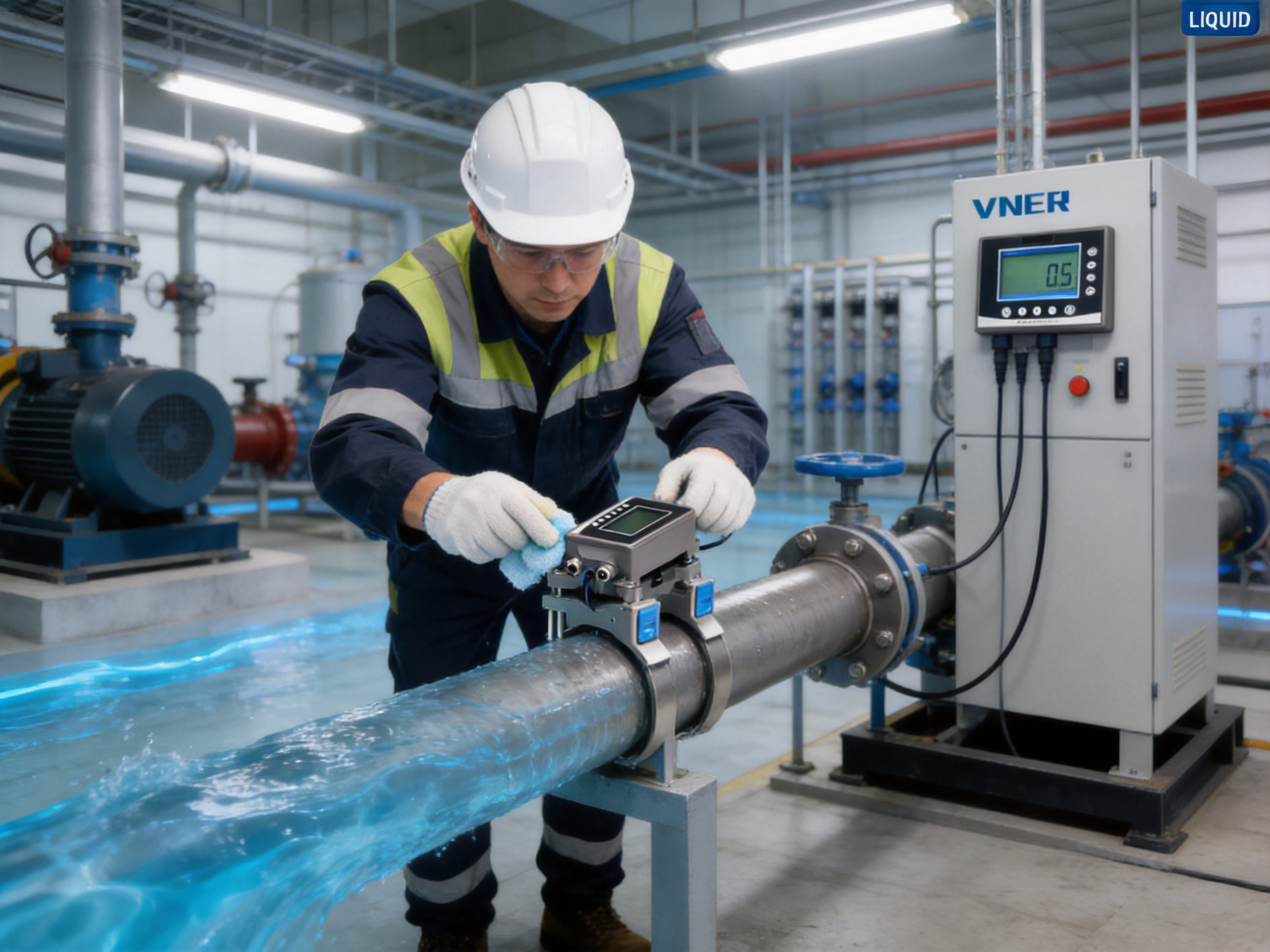
Selection and Application Checklist
Before ordering or installing the VNFT211, the user should confirm that the application matches the product’s measurement range and operating conditions. The most important questions concern pipe size, pipe material, liquid composition, temperature, flow behavior, installation space, and required outputs.
- Is the pipe within the DN15–DN65 range?
- Is the pipe made from metal or a compatible rigid plastic?
- Is the liquid clean, single-phase, and sufficiently homogeneous?
- Does the pipe remain full at the proposed measuring location?
- Is the liquid temperature within 0–115 °C?
- Can the transducers be mounted securely on the pipe exterior?
- Is there a suitable section away from severe turbulence?
- Is a local display required?
- Should the system provide 4–20 mA, Modbus RS485, pulse, or relay outputs?
- Is cooling or heating energy measurement required?
- Will the enclosure be protected from condensation, freezing, chemicals, and excessive sunlight?
- Is calibration required to achieve the highest available accuracy?
Answering these questions before installation helps prevent avoidable commissioning delays. A manufacturer or qualified application engineer can review unusual pipe construction, high-temperature service, limited straight-run conditions, heavy deposits, or liquids containing significant gas or solids.
Lifecycle and Cost Advantages
The total value of a flow meter includes more than its purchase price. Installation labor, production interruption, pipeline modification, commissioning, maintenance, energy impact, and future flexibility can all influence lifecycle cost. The VNFT211 addresses several of these factors through its external installation design.
Because the pipe usually does not need to be cut, the project may require fewer mechanical components and less specialized labor. The facility may avoid welding, flange work, temporary bypass piping, draining, cleaning, and extended recommissioning. These savings can be particularly significant when the pipeline is located in a production area or when shutdown opportunities are rare.
The absence of internal moving parts can reduce routine mechanical maintenance. There is no rotor to replace and no wetted electrode to inspect. The external sensor arrangement also allows service personnel to access the measurement hardware without opening the process line.
The meter’s communication options can create further value by making flow data available to control and energy-management systems. Better data can support pump optimization, leak investigation, equipment balancing, preventive maintenance, and more accurate allocation of water or thermal energy.
Future flexibility is another advantage. A clamp-on instrument can be removed or relocated more easily than an inline meter when equipment is rearranged. This is useful for pilot plants, rental facilities, temporary production areas, process improvement programs, and projects where the final pipe configuration has not yet been fixed.
Frequently Asked Questions
What principle does the VNFT211 use?
The VNFT211 uses transit-time ultrasonic measurement. Two external transducers send and receive ultrasonic signals in upstream and downstream directions. The difference between the signal travel times is used to calculate liquid velocity and flow rate.
Does the meter need to contact the liquid?
No. The transducers are mounted outside the pipe. The instrument measures through the pipe wall and does not require wetted electrodes, an insertion probe, or an internal rotating element.
Can it be installed without shutting down the pipeline?
In many applications, yes. Since the meter is clamp-on, it normally does not require cutting or draining the pipe. Site safety procedures and the condition of the pipe must still be reviewed before installation.
What pipe sizes does it support?
The VNFT211 is designed for DN15–DN65 pipelines, making it suitable for small-diameter industrial, HVAC, utility, laboratory, and packaged-equipment applications.
Which pipe materials are compatible?
It is suitable for metal pipes and rigid plastic pipes such as PVC, PP, and PVDF, provided that the pipe construction and surface condition allow reliable ultrasonic transmission.
Which liquids can be measured?
The meter is intended for water and other clean, single-phase liquids without significant solid particles or impurities. Applications with large quantities of air, gas, suspended solids, or multiphase flow should be evaluated carefully.
What accuracy can be expected?
The standard accuracy is ±2%. After suitable calibration and under appropriate application conditions, accuracy of ±1% may be achieved.
What temperature range is supported?
The stated liquid temperature range is 0 to 115 °C. The pipe surface must not be frozen, and the transducers and enclosure must remain within their applicable environmental limits.
Does the meter display accumulated flow?
Yes. The 256 × 128 LCD can display flow rate, accumulated flow, status information, and alarms.
Can it connect to a PLC or DCS?
Yes. The standard 4–20 mA output supports conventional analog control systems, while Modbus RS485 supports digital communication. Pulse and relay outputs are available as options.
Can it measure cooling or heating energy?
Yes. The meter can be configured as an ultrasonic cooling or heating energy meter when suitable temperature measurement components and system configuration are provided.
Why is a low-flow cutoff useful?
The factory low-velocity cutoff of 0.08 m/s helps prevent very small signal variations from being interpreted as meaningful flow. This can improve the quality of readings and totalized data when the system is stopped or operating at extremely low flow.
Is the response time adjustable?
Yes. The response time can be adjusted from 0.5 to 60 seconds. Faster settings respond more quickly to changes, while longer settings can provide a smoother indication in fluctuating systems.
What installation conditions are most important?
The pipe should be full, the liquid should be reasonably clean and homogeneous, the external pipe surface should be clean, and the transducers should be mounted firmly. A stable pipe section away from strong turbulence is preferred.
Who manufactures the instrument?
The instrument is manufactured by Jiangsu VNER Electronic Technology Co., Ltd., an industrial flow measurement company with experience in ultrasonic, electromagnetic, Coriolis, vortex, swirl, turbine, thermal mass, and rotameter technologies.
Conclusion
The VNFT211 Clamp-On Ultrasonic Flow Meter is a practical small-pipe measurement solution for facilities that need reliable flow information without modifying existing pipelines. Its transit-time ultrasonic principle enables external measurement through the pipe wall, avoiding wetted components, internal obstructions, and many of the installation challenges associated with inline instruments.
Its DN15–DN65 range makes it particularly relevant to branch lines, HVAC circuits, packaged equipment, laboratories, utility systems, and compact industrial installations. The 256 × 128 LCD provides clear local information, while 4–20 mA, Modbus RS485, pulse, and relay options support automation and remote monitoring. The optional cooling and heating energy function extends the product from basic flow indication to thermal-energy management.
Compared with conventional intrusive meters, the VNFT211 can reduce installation time, minimize pressure loss, avoid process contamination, and support retrofit work with limited downtime. Its value is strengthened by adjustable response time, low-flow cutoff, EEPROM data retention, protective electrical functions, IP65 enclosure protection, and compatibility with metal and rigid plastic pipes.
The product is supported by the manufacturing and engineering resources of Jiangsu VNER Electronic Technology Co., Ltd., including a broad flow-meter portfolio, in-house calibration, quality processes, technical personnel, modern production facilities, and experience across international industrial projects. For users seeking an efficient way to measure clean-liquid flow in existing small-diameter pipelines, the VNFT211 offers a flexible alternative to permanent intrusive installation.
References
1. Product technical information for the VNFT211 Clamp-On Ultrasonic Flow Meter.
2. General principles of transit-time ultrasonic flow measurement and external transducer installation.
3. Industrial instrumentation practices for 4–20 mA analog transmission and Modbus RS485 communication.
4. Application guidance for HVAC chilled-water, heating-water, and thermal-energy monitoring systems.
5. General engineering practices for flow-meter installation in full pipes and stable-flow sections.
6. Manufacturer information concerning industrial flow measurement products, calibration, quality processes, and engineering support.
Product: VNFT Clamp-On Ultrasonic Flow Meter



Products
Contact Information
-

+86 18652789521
+86-0514-83633600 / 83633900 -

+86-0514-83633600 / 83633900
-

s@vner.com.cn
katherine@vner.com.cn -

No. 11 Xingye Road, Chenji Town Industrial Park, Yizheng, Yangzhou, China
