
 0
0
 EN
EN  English
 عربى
عربى Español
 русский
If you need any help, please feel free to contact us
Home / Author / Guo Lanyue — Industrial Flow Meter Sales Manager / ST51 Series Thermal Mass Flowmeter: Direct Gas Measurement for Efficient Industrial Process Control
ST51 Series Thermal Mass Flowmeter: Direct Gas Measurement for Efficient Industrial Process Control
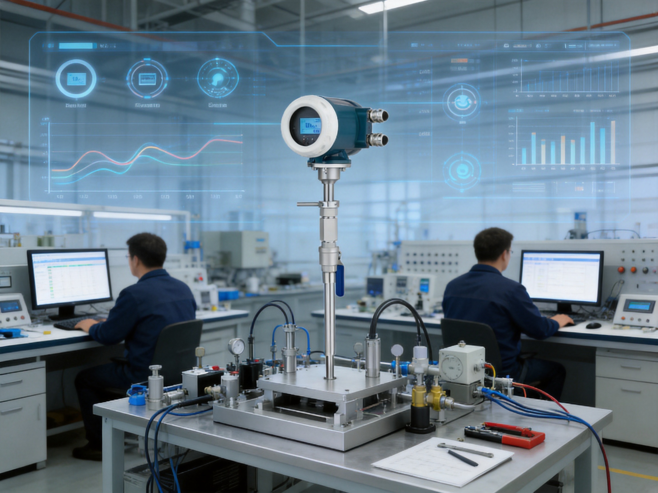
Accurate gas measurement is essential wherever fuel consumption, process stability, equipment protection, environmental performance, and energy efficiency depend on reliable flow data. Gas applications are often more demanding than liquid applications because gas density changes significantly with pressure and temperature. A conventional volumetric flowmeter may therefore require additional transmitters, compensation algorithms, and complex installation arrangements before its readings can be used for meaningful process decisions.
The ST51 Series Thermal Mass Flowmeter is designed to address these challenges through direct thermal mass flow measurement. Using a constant-temperature-difference thermal dispersion principle, the instrument measures gas mass flow and gas temperature without requiring separate external pressure and temperature compensation under suitable operating conditions. The result is a compact and practical solution for clean gas systems in industrial plants, energy networks, utilities, environmental monitoring installations, and process equipment.
The meter combines a sensitive thermal sensor, a robust stainless-steel wetted construction, and an intelligent modular transmitter. It is available in in-line configurations for smaller pipelines and insertion configurations for larger round or rectangular ducts. With negligible pressure loss, fast response, a wide measuring range, and communication options such as Modbus RS485 and HART, the ST51 Series can support both local operation and integration with modern PLC, DCS, SCADA, and energy-management systems.
Understanding the Need for Direct Gas Mass Measurement
Gas flow can be expressed in several ways, including actual volumetric flow, standard volumetric flow, and mass flow. Actual volumetric flow describes the volume occupied by the gas at the operating pressure and temperature. Standard volumetric flow converts the gas volume to defined reference conditions. Mass flow expresses the amount of gas independent of the volume occupied by that gas.
For many industrial applications, mass flow is the most useful measurement. Fuel purchasing, boiler efficiency calculations, gas allocation, chemical dosing, inerting, combustion control, and compressed-air energy management are generally related to the quantity of gas rather than its instantaneous volume. However, gas volume changes with pressure and temperature, so a volumetric meter may require external compensation to calculate a dependable mass or standard volume value.
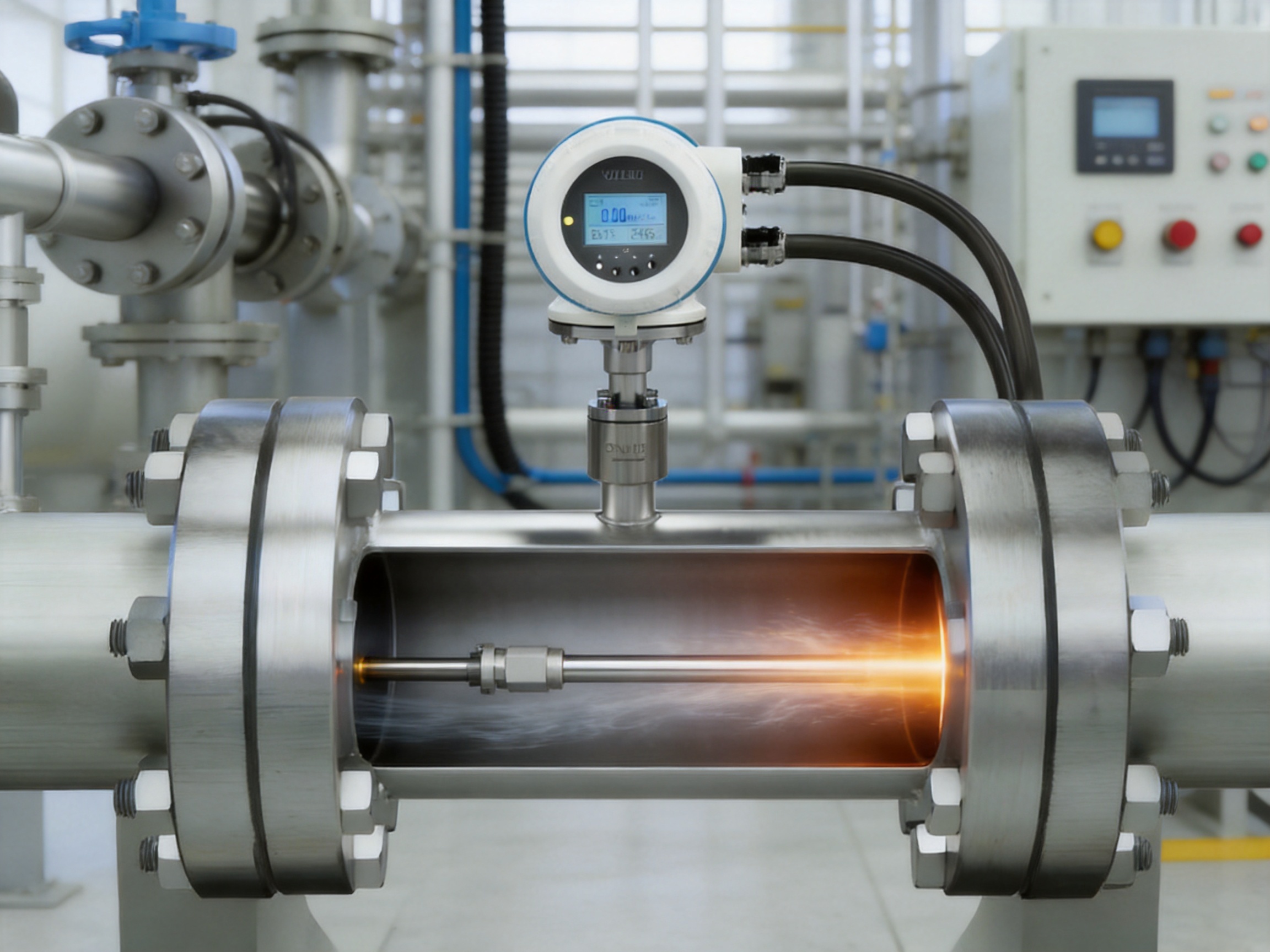
The ST51 Series uses thermal dispersion technology to measure the effect of flowing gas on a heated sensor. As gas passes over the sensor, it removes heat. The amount of heat transferred depends on the gas flow and its thermal properties. By maintaining a constant temperature difference between the heated sensor and a reference sensor, the electronics can determine the relationship between heat loss and gas mass flow.
This operating principle allows the flowmeter to measure gas mass flow directly. It also enables the instrument to monitor gas temperature through the sensor assembly. Standard volume flow can be calculated internally when the relevant reference conditions and configuration parameters are entered into the transmitter.
Product Overview
The ST51 Series Thermal Mass Flowmeter is intended primarily for clean, single-phase gases, with non-condensing service preferred. It is suitable for gases such as natural gas, city gas, nitrogen, hydrogen, instrument air, compressed air, carbon dioxide, oxygen-enriched air, and other compatible technical gases. Gas composition should remain sufficiently stable for the selected calibration and application conditions.
The series is offered in two principal installation formats. In-line versions are designed for nominal pipeline sizes from DN10 to DN100. These units are installed directly into the process line and are suitable for compact piping systems, gas skids, equipment packages, and branch lines. Insertion versions are used for larger pipelines and ducts. An insertion probe can be installed through a mounting fitting, and a ball-valve arrangement can support hot-tap installation where the process design and safety procedures permit.
The instrument can be supplied with flanged or threaded process connections. Stainless-steel 304 or 316L body materials provide mechanical strength and corrosion resistance for a broad range of industrial gas applications. Sensor materials may include 316L, Hastelloy, PTFE, and ceramic combinations, selected according to medium compatibility and application requirements.
| Item | ST51 Series Specification |
|---|---|
| Measurement principle | Constant temperature-difference thermal mass flow based on thermal diffusion |
| Measured medium | Clean gases; single-phase and non-condensing service preferred |
| Measured variables | Gas mass flow and gas temperature; standard volume flow through internal calculation |
| Accuracy | ±1.0% of reading plus ±0.5% of full scale under specified conditions |
| Nominal in-line size | DN10 to DN100 |
| Insertion installation | Large round or rectangular ducts and pipelines |
| Process connection | Flanged, threaded, or insertion connection with optional ball valve |
| Operating pressure | 1.0 to 6.3 MPa |
| Flange compatibility | ANSI 150 and ANSI 300 options |
| Gas temperature range | -40 to +300 °C, depending on model |
| Enclosure protection | IP67 |
| Output signals | 4-20 mA and pulse frequency output |
| Communication | Modbus RS485 and HART |
| Power supply | 24 VDC or 220 VAC |
| Explosion protection | Ex d explosion-proof versions available for applicable models |
How Constant-Temperature-Difference Thermal Measurement Works
The thermal sensor assembly generally includes a heated sensing element and a temperature reference element. The transmitter supplies electrical energy to the heated element and maintains a defined temperature difference between the two sensors. When the gas is stationary or moving slowly, heat loss from the heated element is relatively low. As gas velocity increases, more heat is carried away and the electrical power required to maintain the temperature difference changes.
The electronics interpret this change according to the calibration characteristics of the instrument and the selected gas conditions. Because the measurement is related to the mass of gas passing the sensor, the meter can provide a direct mass flow signal without the same type of external pressure and temperature compensation arrangement normally associated with many volumetric measurement systems.
The thermal principle provides several practical benefits. The sensor has no rotating impeller, bearings, gears, or other moving mechanical parts. This reduces mechanical wear and helps maintain stable performance over long operating periods. The sensor is also highly responsive to changes in gas flow, making the meter useful for variable-demand systems and control loops that need rapid feedback.
Thermal dispersion measurement is particularly attractive for low-density gases and low-flow conditions. A properly selected thermal meter can detect changes that may be difficult to measure with less sensitive technologies. Nevertheless, accurate selection remains important. Gas composition, moisture, contamination, installation profile, pipe size, pressure, temperature, and flow range should all be evaluated before ordering.
Key Advantages Over Conventional Gas Flow Solutions
Direct mass flow measurement
The main advantage of the ST51 Series is its ability to measure gas mass flow directly. In many applications, the user does not need to install separate pressure and temperature transmitters solely for flow compensation. This can reduce instrument count, wiring, junction boxes, engineering work, and commissioning time.
Fewer separate components can also simplify maintenance. Instead of coordinating the calibration and failure diagnosis of multiple instruments, the plant team can use one integrated flowmeter for the primary gas measurement. The transmitter can display mass flow, totalized flow, gas velocity, and temperature, depending on the selected configuration.
Negligible pressure loss
Thermal flowmeters introduce very little obstruction into the gas stream. The absence of a large internal restriction is important in compressed-air systems, low-pressure gas networks, ventilation systems, and energy-sensitive installations. A high pressure loss would force compressors, blowers, or regulators to work harder, increasing operating costs.
Because the ST51 Series is designed for negligible pressure loss, it can monitor gas consumption without significantly changing the process it is measuring. This is a major benefit compared with primary elements that create a substantial differential pressure and may require additional pressure measurement and permanent energy expenditure.
Fast response
A typical response time below 0.5 seconds enables the meter to follow rapid changes in gas demand. This is valuable for burner control, batch operations, pneumatic equipment, inerting systems, and compressor loading management. Fast response also supports leak detection because abnormal flow increases can be identified more quickly.
In control applications, a responsive signal helps the control system correct fuel-air ratios, maintain gas supply targets, or adjust equipment output before a temporary flow disturbance becomes a larger process problem.
No moving parts
The fully welded construction and non-mechanical sensor design eliminate common wear mechanisms associated with moving flowmeter components. There are no turbine bearings to lubricate, no impeller to replace, and no rotating assembly that can be damaged by ordinary mechanical vibration.
This design does not make the meter immune to all service conditions. Excessive contamination, condensation, deposits, unsuitable gas composition, or installation in severe turbulence can still affect measurement performance. However, for clean and properly conditioned gas, the no-moving-parts design supports low maintenance and long-term stability.
Wide measuring range
The ST51 Series offers a wide measuring range, potentially covering several orders of magnitude depending on model selection and application conditions. This makes it suitable for systems where demand changes substantially between operating shifts, production states, or seasonal conditions.
Compressed-air networks provide a typical example. A plant may have low consumption during night hours and high demand during production peaks. A meter with insufficient turndown may fail to capture low-load consumption accurately or may become overloaded during peak periods. A correctly sized thermal meter can provide useful data across both conditions.
Integrated temperature measurement
Gas temperature is measured in addition to mass flow. This information helps operators understand process conditions, verify the validity of standard-volume calculations, and identify abnormal thermal behavior. In combustion-air, heated-gas, dryer, and furnace applications, temperature data can be valuable for process optimization and troubleshooting.
Flexible communications and outputs
The standard 4-20 mA output is widely compatible with PLC and DCS input modules. The pulse output can be used for totalization, batching, counting, or connection to external energy-management equipment. Modbus RS485 enables digital data exchange, remote configuration, and diagnostics. HART communication can support device management and parameter access through compatible host systems.
This combination allows the ST51 Series to serve both simple and advanced installations. A small utility line may require only a local display and analog signal, while a large plant can use digital communications to collect flow, temperature, totalized values, status information, and diagnostic data in a central control room.
Industrial protection options
An IP67 enclosure provides protection against dust and temporary water exposure when properly installed. This supports outdoor installations and industrial areas where the transmitter may encounter rain, washdown, humidity, or airborne particles.
Ex d explosion-proof versions are available for applicable models. These versions may be selected for hazardous-area applications such as fuel gas systems, petrochemical facilities, and selected oil and gas installations. Hazardous-area classification, electrical approvals, cable entry requirements, and local regulations must be confirmed during project design.
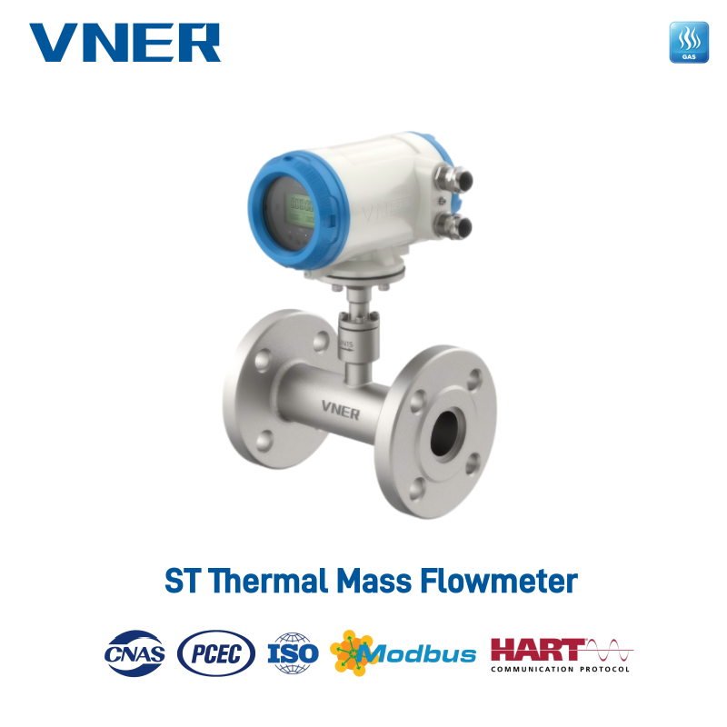
ST51 Series Thermal Mass Flowmeter
Construction and Engineering Design
Stainless-steel process body
The process body is available in stainless steel 304 or 316L. Stainless steel provides good resistance to corrosion, mechanical damage, and temperature variation. The 316L option is particularly useful when the gas or surrounding environment requires enhanced corrosion resistance.
The fully welded design supports structural integrity and reduces the number of potential leakage points. In industrial gas service, the quality of the pressure boundary is as important as the electronic measurement function. Correct welding, dimensional control, surface treatment, pressure testing, and inspection are therefore essential elements of manufacturing quality.
Application-specific sensor materials
Sensor material selection should be based on gas composition, moisture, temperature, pressure, and possible contaminants. The available material combinations include 316L, Hastelloy, PTFE, and ceramic components. Hastelloy may be chosen for more demanding corrosive environments, while PTFE or ceramic elements may be considered when chemical compatibility or elevated-temperature performance requires them.
The final material selection should be confirmed with the manufacturer before production. A thermal sensor calibrated for a particular gas composition may not deliver the same result when used with a substantially different mixture. This is especially important for hydrogen-rich gases, mixed process gases, wet gases, and gases containing heavy hydrocarbons or particulate matter.
Modular transmitter architecture
The intelligent modular transmitter is designed to provide measurement processing, display, configuration, communication, and diagnostic functions in one integrated unit. Modular architecture can simplify product configuration and support different combinations of power supply, communication, display, output, and hazardous-area requirements.
A local or remote LCD can display instantaneous flow, accumulated flow, gas velocity, and temperature. Local access is helpful during commissioning and maintenance, while remote display options may be preferred when the meter is mounted at an elevated position or in a difficult-to-access duct.
Advanced Manufacturing and Quality Strengths
Reliable flow measurement depends not only on the operating principle but also on manufacturing discipline. Sensor geometry, welding quality, electronic calibration, material consistency, sealing, and final inspection all influence the performance of a thermal flowmeter. Jiangsu VNER Electronic Technology Co., Ltd. applies an engineering-focused manufacturing approach to industrial flow instrumentation.
The company operates modern facilities across three plants, with approximately 23,000 square meters of production and engineering space. A technical team of more than 150 people supports product development, application engineering, calibration, production, testing, and customer service. Since 2011, the company has developed solutions covering electromagnetic, Coriolis, vortex, swirl, turbine, thermal mass, ultrasonic, and rotameter technologies.
This broad product portfolio is valuable because gas measurement requirements vary widely. Thermal mass meters are well suited to clean gases, while other technologies may be more appropriate for liquids, slurries, high-pressure fluids, or applications requiring different measurement characteristics. Experience across multiple flow technologies helps engineers select the right instrument rather than forcing every application into one product category.
In-house calibration capability
Calibration is central to thermal flowmeter production. The relationship between sensor heat transfer and gas flow must be established with controlled reference conditions. In-house calibration capabilities allow the manufacturer to manage important parts of the testing process, verify production units, and maintain greater control over traceability and consistency.
A controlled calibration process can include verification of zero stability, span performance, response behavior, temperature indication, output linearity, communication functions, and alarm or diagnostic status. The precise tests depend on the model and order specification, but the objective is consistent: every finished instrument should conform to its defined performance requirements before shipment.
Engineering-driven sizing and selection
Incorrect sizing is one of the most common causes of unsatisfactory flowmeter performance. A meter selected only by nominal pipe size may be poorly matched to the actual gas flow range, pressure, temperature, or gas composition. Engineering-driven selection considers minimum and maximum flow, normal operating flow, line pressure, gas temperature, density, installation orientation, straight-run requirements, and the presence of disturbances.
The manufacturer supports EPC contractors, end users, and OEM partners with application evaluation and product selection. This is particularly important for insertion meters because probe location and insertion depth have a direct effect on the velocity profile sampled by the sensor.
Automated and repeatable production
Increasing automation can improve repeatability in assembly, electronic testing, parameter loading, and quality verification. Automation does not replace engineering judgment; instead, it helps reduce variation in repetitive operations and supports process traceability.
For an industrial flowmeter manufacturer, repeatable production is important for OEM projects and multi-point installations. When dozens or hundreds of meters are supplied for one plant, consistent configuration, labeling, calibration records, and communication settings can reduce commissioning time and simplify spare-parts management.
Quality processes and traceability
Industrial customers often require documentation covering materials, calibration, pressure testing, inspection, and final acceptance. Certified quality processes and traceability systems help connect the finished meter with its manufacturing records, configured parameters, and test results.
Traceability is especially valuable in safety-related gas applications, export projects, and regulated industrial environments. It also supports service investigations when a customer needs to review the original instrument configuration or determine whether operating conditions have changed since commissioning.
Installation Options for Different Gas Systems
In-line installation
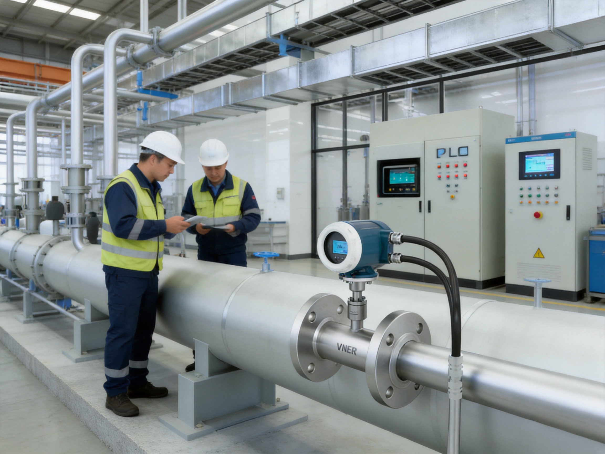
In-line ST51 meters are available for DN10 to DN100 pipelines. They are suitable for branch gas lines, utility skids, burner trains, laboratory and pilot equipment, process gas feeds, and compact plant piping. In-line installation provides a defined flow path through the meter and is often selected where the pipe size is within the supported range.
Before installation, the pipe should be cleaned to prevent oil, weld slag, rust, thread sealant, or other debris from contacting the sensor. The flow direction indicated on the meter should match the actual gas direction. The meter should be installed so that condensate cannot accumulate around the sensing element, especially in systems where gas cooling may produce moisture.
Insertion installation
Insertion meters are appropriate for larger pipes, headers, ducts, and rectangular channels. They can reduce project cost compared with installing a large full-bore meter, particularly in compressed-air networks, combustion-air systems, and plant utility headers.
Insertion installation requires careful attention to probe position. The sensing element should be placed at a representative point in the cross-section and aligned correctly with the gas flow. The probe should not be installed immediately downstream of elbows, valves, reducers, fans, dampers, or other devices that create strong turbulence unless the installation design has been evaluated accordingly.
A ball-valve hot-tap arrangement can permit installation or removal without fully depressurizing the pipeline, subject to suitable process design, pressure rating, safety controls, and approved operating procedures. Hot-tap work should only be performed by qualified personnel with appropriate permits and risk assessments.
Horizontal and vertical pipelines
The meter can be installed in horizontal or vertical arrangements when the installation meets the application requirements. The preferred orientation depends on gas composition, moisture risk, pipe configuration, and accessibility. For gases that may condense, the installation should avoid creating pockets where liquid can collect on or near the sensor.
Flow conditioning and straight runs
Thermal flowmeters, like all velocity-based instruments, can be affected by distorted flow profiles. Adequate straight pipe upstream and downstream helps the gas develop a more stable velocity distribution. The required straight-run distance depends on the disturbance type, pipe geometry, meter design, and actual process conditions.
Where space is limited, the engineering team may evaluate alternative installation positions, flow conditioners, or reduced pipe disturbances. A careful installation review before construction is usually less expensive than correcting an unstable measurement after commissioning.
Applications Across Industrial Sectors
Natural gas and city gas distribution
Natural gas and city gas systems use flow measurement for boiler fuel management, burner control, sectional metering, energy accounting, and equipment performance analysis. The ST51 Series can measure gas mass flow and temperature directly on suitable gas lines, reducing the need for separate compensation instruments.
In boiler systems, totalized gas consumption can be compared with steam production, hot-water output, or electrical generation. This creates a practical basis for evaluating fuel efficiency and identifying changes in burner or boiler performance.
Nitrogen inerting and blanketing
Nitrogen is widely used to reduce oxygen concentration in storage tanks, reactors, pipelines, and process vessels. Excessive nitrogen consumption increases operating cost, while insufficient flow may compromise safety or product quality. A fast-response thermal meter can provide the control system with immediate flow information.
Modbus or HART communication enables the meter to share flow, temperature, totalized consumption, and status information with a DCS. The resulting data can be used to regulate inert gas supply, verify purge sequences, and identify abnormal consumption.
Compressed-air monitoring and leak detection
Compressed air is one of the most expensive industrial utilities because energy is consumed to compress, dry, distribute, and condition the air. Leaks may remain unnoticed for long periods, especially when production equipment continues to operate normally.
Insertion ST51 meters can be installed on main headers, production areas, and branch lines. By comparing compressor output with production-area consumption during operating and non-operating periods, plant engineers can identify unusual demand and estimate leakage. Wide turndown and negligible pressure loss are important advantages in this application.
Boiler combustion air
Combustion control depends on maintaining a suitable relationship between fuel and air. Too little air may produce incomplete combustion and increased emissions, while excessive air can reduce thermal efficiency by carrying heat out of the stack.
Flow feedback from the ST51 Series can support air-fuel ratio monitoring and combustion optimization where the gas composition and temperature are appropriate for thermal measurement. The high temperature capability available on selected models supports use on hot combustion-air lines and other thermal process systems.
Chemical reactors and dryers
Reactors, dryers, coating systems, and other process equipment often use nitrogen, dry air, hydrogen, or inert gases. Stable gas flow can influence reaction conditions, drying rate, atmosphere control, and product consistency.
The fast response of the ST51 Series helps process control systems respond to changing production loads. Its digital communications can also provide operating data for batch records, equipment diagnostics, and production analysis.
Environmental and exhaust monitoring
Clean vent and exhaust lines may require continuous gas flow monitoring for internal environmental reporting, process optimization, or equipment balance calculations. The meter can provide mass flow and totalized values where the gas is compatible with the sensor and remains sufficiently clean and non-condensing.
For emissions compliance applications, users should verify whether the selected flowmeter meets all applicable local regulatory, calibration, uncertainty, and certification requirements. Thermal mass measurement may be suitable for some clean exhaust streams but may require additional evaluation for wet, dirty, corrosive, or compositionally variable gases.
Food and beverage processing
Carbon dioxide and nitrogen are used in carbonation, packaging, storage, and atmosphere control. Compressed air is also common in pneumatic systems. Flow monitoring can help reduce gas waste, maintain packaging consistency, and improve utility allocation between production lines.
Material compatibility, hygiene requirements, cleaning practices, and installation location should be considered when selecting a meter for food and beverage service. The process connection and wetted materials should be matched to the relevant plant standards.
Electronics and semiconductor production
Clean dry air and nitrogen are used extensively in semiconductor manufacturing, coating, packaging, and controlled-atmosphere processes. These applications often require stable flow, low contamination risk, rapid response, and reliable data communication.
The ST51 Series can support process gas monitoring when the gas is clean, dry, and compatible with the selected sensor materials. Its compact in-line versions are useful for equipment-level monitoring, while insertion versions can be applied to larger facility utility lines.
Steel, glass, and metallurgy
Furnaces, kilns, reheating systems, and glass-processing equipment consume combustion gases and oxygen-enriched air. Flow measurement assists with fuel balancing, combustion control, furnace efficiency, and process repeatability.
Selected ST51 models can operate with gas temperatures up to approximately 300 °C. The actual temperature limit depends on model configuration, sensor construction, electronics placement, and installation conditions. High-temperature applications should be reviewed carefully before selection.
Application Comparison with Other Flowmeter Technologies
No single flowmeter technology is ideal for every fluid and process. The strength of the ST51 Series is its combination of direct gas mass measurement, low pressure loss, sensitivity, and practical installation options. Comparing technologies helps users understand when a thermal meter is the right choice.
| Technology | Typical Strength | Potential Consideration for Clean Gas Service |
|---|---|---|
| Thermal mass | Direct gas mass measurement, fast response, low pressure loss, wide range | Gas composition, moisture, contamination, and thermal properties should be evaluated |
| Gas turbine | Good repeatability for suitable clean gases and established flow ranges | Moving parts require attention to wear, lubrication, and contamination |
| Vortex | Versatile measurement for gases, steam, and some liquids | May require compensation for mass or standard-volume calculations; needs suitable velocity and flow conditions |
| Orifice or differential pressure | Broad industrial familiarity and standardized installation practices | Creates permanent pressure loss and normally requires pressure and temperature compensation for gas mass flow |
| Coriolis mass | Highly direct mass measurement and density information | Often more expensive and heavier for large gas lines; pressure drop and installation constraints may be important |
| Ultrasonic | Suitable for selected large-line and non-invasive applications | Performance depends on gas properties, acoustic conditions, installation, and signal quality |
The comparison does not mean that thermal measurement should replace every other technology. Instead, it shows why the ST51 Series is attractive for clean gas lines where pressure loss must be minimized and direct mass flow data is preferred. For dirty gases, wet gases, highly variable compositions, or applications requiring certified custody transfer performance, another technology may be more appropriate.
Configuration, Commissioning, and Operation
Before commissioning, the user should confirm that the meter model matches the gas type, expected flow range, pressure, temperature, pipe size, and installation arrangement. The transmitter should be configured with the correct engineering units, reference conditions for standard volume calculations, output ranges, pulse settings, communication parameters, and alarm thresholds.
The pipeline should be checked for leaks, vibration, unexpected bypass flow, and obstructions. Electrical wiring must follow the applicable power-supply and hazardous-area requirements. The meter should be allowed to stabilize according to the operating instructions, particularly when the gas temperature differs substantially from the ambient temperature.
During commissioning, the displayed temperature and flow should be compared with reasonable process expectations. If an independent reference instrument is available, the readings can be reviewed under several operating points. The 4-20 mA output, pulse output, Modbus registers, HART variables, and local display should all be verified where those features are included in the order.
For insertion meters, commissioning should include confirmation of insertion depth and probe orientation. The sensor must be positioned in the intended portion of the flow profile. A probe installed too close to a wall or incorrectly aligned may produce a biased reading even when the electronics and sensor are functioning correctly.
Maintenance and Long-Term Reliability
The no-moving-parts design reduces routine mechanical maintenance, but periodic inspection remains important. Users should check the enclosure, cable glands, grounding, process connections, display condition, and communication status. In applications where deposits or contamination are possible, the sensor should be inspected according to a risk-based maintenance schedule.
Sensor contamination may act as an insulating layer and change the heat-transfer relationship. Condensation can also affect the thermal response. If the process gas is not clean and dry, upstream filtration, separation, heating, or drainage may be needed. The meter should not be treated as a substitute for proper gas conditioning.
Diagnostic functions can support maintenance planning and fault tracing. Sensor, electronics, and status self-checks may help identify abnormal conditions before they cause a complete measurement failure. Digital communication can allow maintenance personnel to review status information without opening the transmitter enclosure.
Periodic verification may be performed by comparing the meter with a calibrated reference, a plant balance, or a controlled test condition. The appropriate interval depends on application criticality, gas cleanliness, regulatory requirements, operating stability, and the consequences of measurement error.
Selection Guidelines
Users should provide complete application data when requesting an ST51 Series Thermal Mass Flowmeter. The most important information includes gas name and composition, minimum and maximum flow, normal flow, line size, operating pressure, gas temperature, ambient temperature, process connection, installation orientation, required output, communication protocol, hazardous-area classification, and material compatibility requirements.
Gas composition is especially important for thermal technology. A meter calibrated for natural gas may not produce the same accuracy when used with nitrogen, hydrogen, carbon dioxide, or a changing process mixture. For mixed gases, the manufacturer should review the composition and determine whether a dedicated calibration or alternative instrument is required.
Condensation and particulate contamination should also be disclosed. A gas described as “clean” may still contain oil aerosol, dust, welding residue, or moisture during startup and abnormal operation. The installation may need filters, coalescers, separators, drains, or heat tracing to protect the sensor and stabilize the measurement.
The flow range should be specified in mass units or clearly defined reference volume units. Mixing actual volume flow and standard volume flow without stating pressure and temperature conditions can lead to incorrect sizing. A proper selection should consider the lowest flow that must be measured, not only the normal or maximum flow.
Why the ST51 Series Supports Modern Industrial Management
Industrial measurement is increasingly connected to energy-management platforms, predictive maintenance systems, and production analytics. A flowmeter is no longer used only to display a local value. It can become a source of information for identifying waste, comparing production areas, calculating specific energy consumption, and improving equipment availability.
The ST51 Series supports this approach through analog, pulse, and digital outputs. Real-time mass flow can be sent to a control loop, totalized consumption can be recorded for allocation, temperature can be used for process analysis, and diagnostic information can support maintenance decisions.
For companies managing multiple factories or production lines, standardized thermal meters can simplify data collection across natural gas, nitrogen, compressed air, and other technical gas systems. The company’s experience with more than 2,000 engineering projects in over 30 countries also supports applications involving different plant standards, project specifications, and operating environments.
OEM and EPC customers benefit from configurable instruments, engineering assistance, documentation support, and repeatable production. End users benefit from a practical instrument that can be installed on both small process lines and large utility headers. Together, these capabilities make the ST51 Series suitable for new projects, equipment upgrades, and plant-wide metering programs.
Frequently Asked Questions
What does the ST51 Series measure?
The ST51 Series measures gas mass flow and gas temperature. It can also calculate standard volume flow internally when the reference conditions and configuration parameters are correctly defined.
Does the meter require separate pressure and temperature transmitters?
For direct mass flow measurement, separate external pressure and temperature compensation is generally not required under the specified application conditions. Gas temperature is measured by the instrument. Additional transmitters may still be required for other process, safety, control, or regulatory purposes.
What gases can be measured?
The meter is intended for clean gases such as natural gas, city gas, nitrogen, hydrogen, instrument air, compressed air, carbon dioxide, and other compatible technical gases. The manufacturer should review gas composition, moisture, contamination, and thermal properties before final selection.
Can the ST51 Series measure wet or dirty gas?
The preferred medium is clean, single-phase, non-condensing gas. Wet gas, condensation, oil, dust, or deposits may affect the thermal sensor and measurement accuracy. If the application contains these conditions, gas conditioning and an application review are recommended.
What is the response time?
The typical response time is less than 0.5 seconds. Actual behavior depends on model configuration, signal damping, process conditions, and control-system settings.
What is the pressure loss across the meter?
The pressure loss is negligible in normal application conditions. This makes the instrument suitable for low-pressure gas systems and energy-sensitive compressed-air or utility networks.
What pipe sizes are supported?
In-line versions are available for DN10 to DN100. Insertion versions can be used in larger round pipelines and rectangular ducts when the probe is correctly positioned and installed.
Can the meter be installed without shutting down the pipeline?
Insertion versions with a ball-valve process connection can support hot-tap installation where the design, pressure rating, safety procedures, and local regulations allow it. Hot-tap work must be performed by qualified personnel.
What output signals are available?
The standard output configuration includes 4-20 mA and pulse frequency output. Modbus RS485 and HART communication are available for digital integration, remote configuration, and diagnostics.
Is a local display available?
Integral or remote LCD options are available depending on the model and configuration. The display can show instantaneous flow, totalized flow, gas velocity, and temperature.
Can the instrument be used in hazardous areas?
Ex d explosion-proof versions are available for applicable models. The required certification and enclosure configuration must match the hazardous-area classification and project regulations.
What materials are available for the sensor?
Sensor material combinations may include 316L, Hastelloy, PTFE, and ceramic components. The selection depends on gas composition, corrosion risk, temperature, and compatibility requirements.
What should be considered when measuring hydrogen?
Hydrogen has distinctive thermal properties and may require dedicated calibration or application evaluation. The gas composition, pressure, temperature, flow range, sensor material, hazardous-area requirements, and calibration conditions should be confirmed before ordering.
How can the meter help detect compressed-air leaks?
Meters can be installed on main headers and branch lines to compare consumption during production and non-production periods. Abnormally high base flow may indicate leaks or equipment that remains open. Totalized and time-based data can help quantify the associated energy loss.
What is the maximum gas temperature?
Selected models can measure gas temperatures up to approximately 300 °C. The actual limit is model-dependent and must be confirmed according to sensor construction, transmitter arrangement, and installation conditions.
Who should select the final meter configuration?
The final selection should be based on complete process data and reviewed by qualified application engineers. Correct sizing and configuration are essential for achieving the stated accuracy and long-term stability.
Conclusion
The ST51 Series Thermal Mass Flowmeter provides a direct and efficient approach to clean gas measurement. Its constant-temperature-difference thermal dispersion principle measures gas mass flow and temperature without the normal need for separate external pressure and temperature compensation for the primary measurement. Negligible pressure loss, fast response, wide turndown, no moving parts, and flexible installation options make it suitable for demanding industrial gas systems.
The instrument can support natural gas metering, nitrogen inerting, compressed-air management, boiler combustion control, chemical processing, semiconductor utilities, food and beverage gas systems, furnace operation, and clean vent monitoring. Analog, pulse, Modbus, and HART outputs allow integration into systems ranging from simple local installations to plant-wide digital energy-management platforms.
Its performance is supported by stainless-steel construction, application-specific sensor materials, IP67 protection, optional Ex d designs, in-house calibration, engineering-led selection, repeatable manufacturing, and a technical organization experienced in multiple flow measurement technologies. For users seeking accurate gas data with low installation complexity and low maintenance demand, the ST51 Series is a strong solution when the gas is clean, compatible, and properly conditioned.
References
1. Industrial thermal dispersion flow measurement principles and constant-temperature-difference sensor technology.
2. General engineering practices for gas flowmeter sizing, installation, commissioning, and verification.
3. Process instrumentation guidance for mass flow, standard volume flow, pressure compensation, and temperature compensation.
4. Industrial compressed-air energy management and leak detection practices.
5. Boiler and furnace combustion-control principles, including fuel-air ratio monitoring.
6. Industrial enclosure protection and hazardous-area instrumentation considerations.
7. Manufacturer product information and technical specifications for the ST51 Series Thermal Mass Flowmeter.
Product: ST51 Series Thermal Mass Flowmeter

We offer all our products and services at international standards.
Products
Contact Information
-

+86-18652789521
+86-18052582295
+86-0514-83633600 / 83633900 -

+86-0514-83633600 / 83633900
-

shawn@vnerflow.com
info@vnerflow.com -

No. 11 Xingye Road, Chenji Town Industrial Park, Yizheng, Yangzhou, China
