
 0
 EN
 English
 عربى
 Español
 русский
If you need any help, please feel free to contact us
Home / Author / Ren Xiaotong — Technical Sales Engineer for Gas Flow Meters / Industrial Temperature and Pressure Compensated Swirl Flowmeters for Steam and Gas Measurement
Industrial Temperature and Pressure Compensated Swirl Flowmeters for Steam and Gas Measurement
Introduction
Accurate flow measurement is essential wherever steam, compressed air, nitrogen, fuel gas, process gas, or other industrial media are generated, distributed, consumed, and billed. In many industrial networks, measuring only the operating volumetric flow is not enough. Gas and steam density change significantly with temperature and pressure, meaning that the same pipe volume can represent very different masses or standard volumes under different operating conditions. Without compensation, flow totals may become inaccurate, energy balances may be distorted, and internal cost allocation may be unreliable.
The SA80T-TP Series Temperature/Pressure Compensation Swirl Flowmeter is designed for these demanding measurement tasks. It combines swirl flow measurement with integrated temperature and pressure sensing, allowing the converter to calculate operating volumetric flow, standard volumetric flow, and mass flow according to the configured medium and reference conditions. The result is a compact instrument intended for steam, compressed gas, and industrial energy metering applications.
Unlike a basic volumetric flowmeter that reports only the flow velocity or operating volume, the SA80T-TP Series continuously considers the actual process temperature and pressure. This provides a more representative measurement of the quantity passing through the pipeline, especially in saturated steam, superheated steam, compressed air, nitrogen, fuel gas, and utility gas systems.
The instrument is based on a swirl or vortex-precession measuring principle. It has no moving parts in the flow path and uses a robust flow body, piezoelectric sensing technology as standard, and optional capacitive sensing for selected applications. Its design supports industrial environments where reliability, low maintenance, process compatibility, and practical installation are as important as measurement performance.
Why Temperature and Pressure Compensation Matters
For liquids, operating volumetric flow can often provide a useful indication of process quantity because liquid density changes are relatively limited within a normal operating range. Gases and steam are different. Their density depends strongly on pressure and temperature. When pressure increases, gas density generally rises. When temperature increases, density generally falls. Steam behavior also depends on whether the steam is saturated or superheated and on the relationship between pressure and temperature.
Consider a compressed-air distribution system. A flowmeter installed near the compressor may see a much higher pressure than a meter installed at a production line. If both instruments report only actual operating volume, their readings may not be directly comparable. A standard volume flow value referenced to defined pressure and temperature conditions is more useful for network balancing, leak detection, consumption analysis, and cost allocation.
The same principle applies to steam. A kilogram of steam represents a defined mass, but its volume changes with pressure and temperature. If a plant reports only actual cubic meters per hour, the value may not accurately represent the amount of steam supplied to different users. A compensated mass flow or standard volume output provides a more meaningful basis for boiler performance analysis, energy accounting, and departmental billing.
The SA80T-TP Series addresses this problem by combining three important inputs:
Flow frequency generated by the swirl sensing system.
Temperature measured through the integrated RTD channel.
Pressure measured through the integrated pressure sensor.
Using these inputs, the converter performs real-time density calculation. The calculation is based on configured media parameters, reference conditions, and standard thermodynamic correlations. This approach allows the instrument to provide compensated values while keeping the installation simpler than a system built from several separate instruments and an external flow computer.
Product Principle and Measurement Architecture
Swirl Flow Measurement
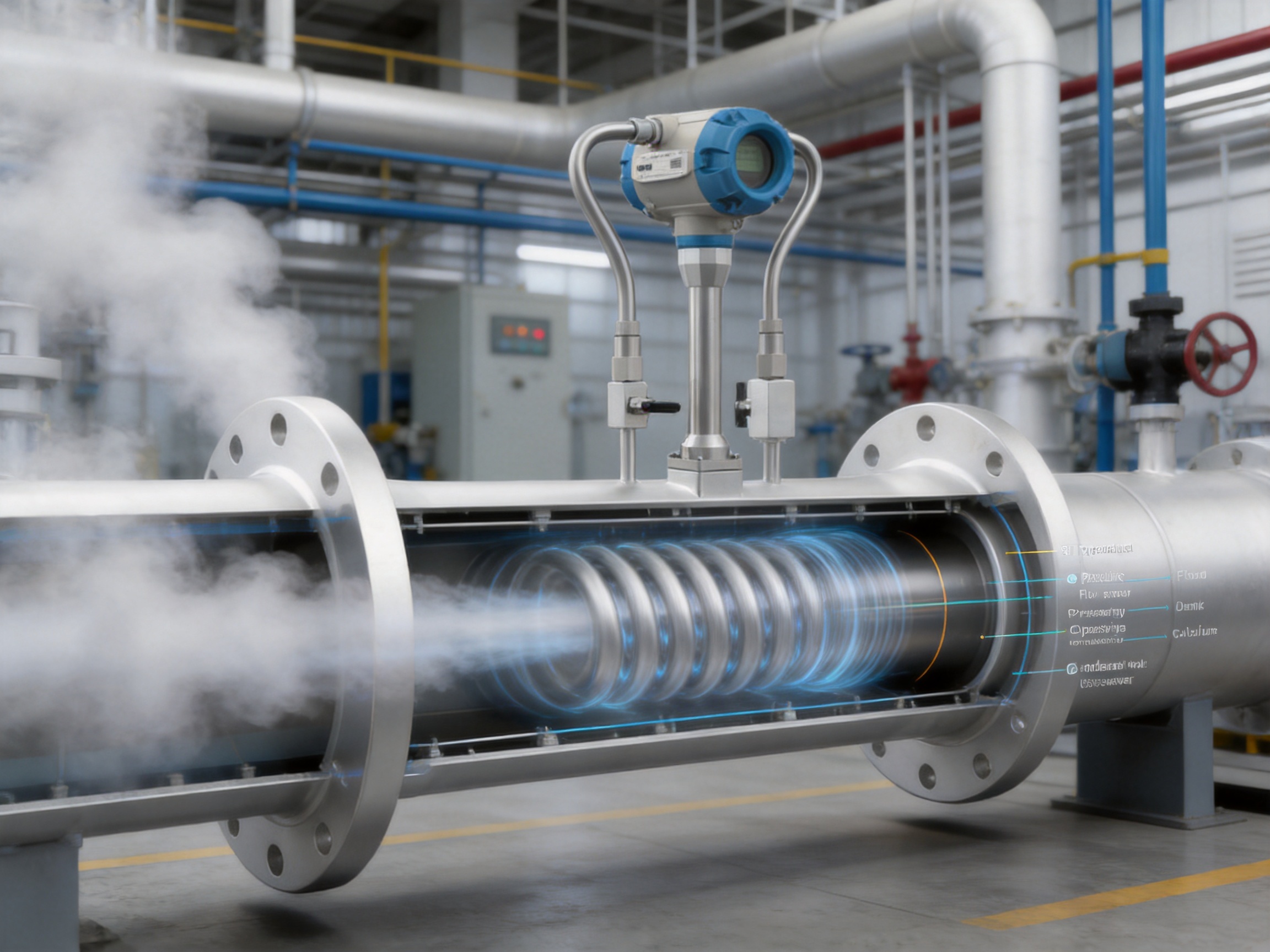
The SA80T-TP Series uses a swirl or vortex-precession principle. Inside the flow body, a specially designed swirl generator causes the process medium to rotate. As the rotating flow develops downstream, the center of the vortex moves in a precessing pattern. The frequency of this precession is related to the volumetric flow rate.
The sensor detects the pressure fluctuations or flow disturbances associated with the precession. The electronic converter then processes the frequency signal and converts it into an operating volumetric flow value. Because the relationship between frequency and flow is established through instrument design and calibration, the meter can provide stable measurement without mechanical rotors, bearings, gears, or other moving components.
The absence of moving parts is a major advantage in industrial service. Mechanical turbine meters, for example, may experience wear, bearing friction, or performance changes when exposed to contamination or long-term operation. A swirl meter avoids these mechanical failure points. This supports longer service life and reduces routine maintenance requirements.
Integrated Temperature Measurement
The integrated temperature channel provides the converter with a real-time process temperature value. This is particularly important for gas and steam applications, where temperature changes directly affect density. The standard design uses an RTD-based temperature measurement channel, allowing the instrument to incorporate the measured value into its compensation calculation.
Temperature data may also help users identify abnormal operating conditions. For example, an unexpected change in steam temperature can indicate a transition between saturated and superheated operation, a control-valve issue, insufficient heating, or a process disturbance. In a compressed-gas network, temperature data can support analysis of compressor discharge conditions, aftercooler performance, and thermal changes along the distribution system.
Integrated Pressure Measurement
The integrated pressure sensor provides the second major compensation input. Pressure is essential for calculating gas and steam density, particularly when the pipeline operates at elevated pressure or when pressure varies throughout the day.
By measuring pressure at the flowmeter location, the converter can avoid relying on a fixed assumed pressure that may not represent actual process conditions. This is valuable in plant utility systems, where demand fluctuations, control-valve adjustments, compressor cycling, or boiler-load changes can cause pressure to vary continuously.
Real-Time Density Calculation
The flow converter combines the measured flow frequency, process temperature, and process pressure. For configured gases and steam, it calculates the applicable density or conversion factor and produces compensated outputs. Depending on the selected medium and configuration, the instrument can report mass flow and standard volumetric flow in addition to operating volumetric flow.
This architecture reduces the need for separate temperature transmitters, pressure transmitters, signal conditioners, and external calculation systems. It can also reduce wiring, cabinet space, engineering work, and the number of instruments requiring calibration and maintenance.
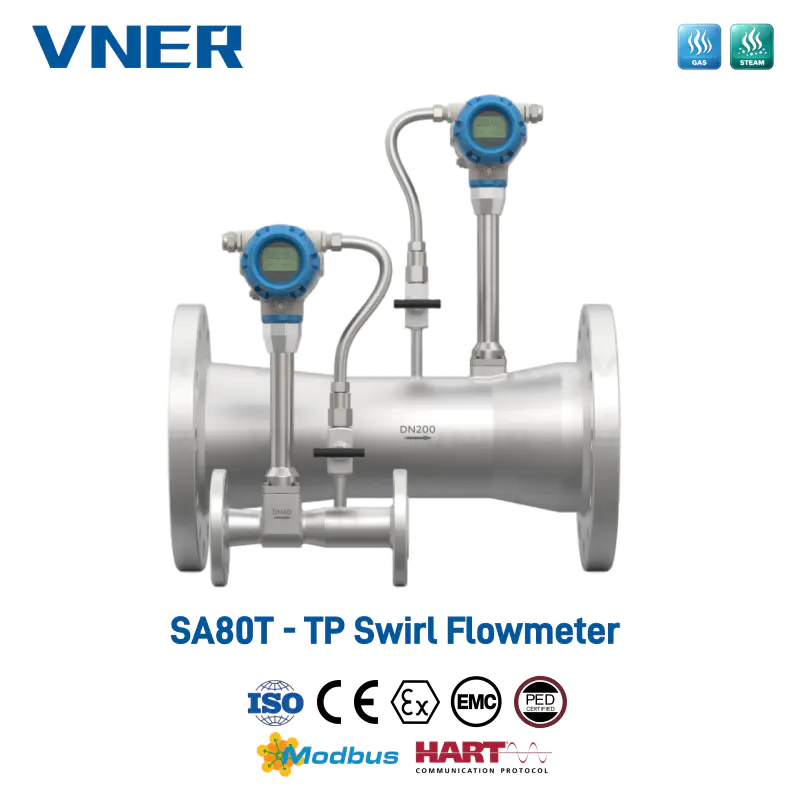
SA80T-TP Series Temperature/Pressure Compensation Swirl Flowmeter
Main Product Advantages
One Instrument for Flow, Temperature, and Pressure
A major advantage of the SA80T-TP Series is its integrated measurement architecture. Conventional systems may require a primary flowmeter, a separate pressure transmitter, a separate temperature sensor, and an external flow computer. Each additional device adds installation points, cable routes, configuration tasks, calibration records, and potential failure modes.
The integrated design brings the essential measurement functions into one coordinated instrument. This simplifies engineering for steam and compressed-gas systems while maintaining access to the process data needed for compensation. The result is a cleaner installation and a more direct relationship between measured flow and calculated quantity.
Compensated Flow for Steam and Gas Networks
The meter is designed for applications in which compensated values are essential. These include boiler outlets, main steam headers, process steam branches, compressed-air networks, nitrogen distribution lines, fuel-gas systems, and plant utility metering.
For steam users, compensated flow can support energy balance, boiler efficiency monitoring, steam distribution management, and production cost allocation. For compressed-gas users, standard volume or mass flow can support leak detection, compressor management, production-line benchmarking, and utility billing.
No Moving Parts
The fully welded flow path and non-mechanical sensing structure provide a robust alternative to meters that depend on moving internal components. There are no turbine blades, shafts, bearings, or impellers to wear in normal operation. This makes the instrument suitable for continuous industrial service and helps reduce maintenance caused by mechanical deterioration.
The no-moving-parts design is also helpful where the process medium may contain small quantities of contamination or where maintenance access is restricted. The application must still be evaluated carefully, because excessive solids, liquid carryover, severe vibration, or unsuitable installation conditions can affect any flowmeter. However, the swirl design provides a practical balance between durability and measurement capability.
Broad Medium Compatibility
The SA80T-TP Series can be configured for liquids, gases, saturated steam, and superheated steam, subject to the selected model, materials, temperature rating, pressure rating, and application conditions. Its primary compensation benefits are directed toward gases and steam, but the underlying swirl flow body can also support broader industrial flow measurement requirements.
Available body and flange materials include carbon steel, stainless steel 304, and stainless steel 316L. Sensor wetted materials may include SS304, SS316L, Hastelloy C, Hastelloy B, and titanium. These material choices allow the instrument to be matched to different process fluids, corrosion risks, temperature ranges, and plant standards.
Flexible Outputs and Communication
The meter provides 4–20 mA and pulse outputs. These outputs can be assigned to operating flow, compensated flow, mass flow, or other configured variables, depending on the instrument setup. HART and Modbus RTU communication are available as options for remote configuration, diagnostic access, and reading of measured and calculated values.
Digital communication is particularly valuable in large plants where instruments are connected to distributed control systems, supervisory systems, energy-management platforms, or plant-wide asset-management software. Operators can obtain process values without visiting each meter, while maintenance teams can review configuration and diagnostic information more efficiently.
Practical Turndown and Accuracy
The typical turndown ratio can reach up to 1:20, depending on the medium, meter size, Reynolds number, installation conditions, and process stability. Typical volumetric-flow accuracy is stated as ±0.5 percent of rate for liquids and ±1.0 percent of rate for gases and steam under calibrated conditions.
Actual application performance depends on correct sizing, appropriate installation, stable process conditions, proper grounding where applicable, suitable straight-pipe lengths, and accurate configuration of the measured medium. The stated values should therefore be treated as application-based performance specifications rather than universal results for every installation.
Comparison with Alternative Flow Measurement Technologies
Compared with Basic Vortex Flowmeters
A conventional vortex flowmeter can measure volumetric flow effectively, but it may not include integrated pressure and temperature measurement. When gas or steam density varies, the user may need to add external instruments and a separate calculation system.
The SA80T-TP Series extends the basic vortex or swirl concept by integrating the key compensation inputs. This is a significant advantage for projects where the objective is not merely to measure actual pipe volume but to obtain a compensated quantity for reporting, control, or energy management.
Compared with Turbine Flowmeters
Turbine flowmeters are widely used for clean liquids and gases, but their rotating components can be sensitive to wear, contamination, lubrication issues, and changes in mechanical friction. They may require upstream filtration or more frequent inspection in difficult services.
The swirl meter eliminates internal rotating elements. It can therefore offer a lower-maintenance solution for many steam and utility-gas applications, particularly where the process is clean or slightly contaminated and where reliable long-term operation is important.
Compared with Electromagnetic Flowmeters
Electromagnetic flowmeters are highly effective for conductive liquids, slurries, and water-based media. However, they are not suitable for dry gases, compressed air, or steam. Their application depends on the electrical conductivity of the measured fluid.
The SA80T-TP Series addresses a different range of applications, especially steam and gas measurement. It can be selected where an electromagnetic meter cannot operate because the medium is nonconductive or gaseous.
Compared with Coriolis Mass Flowmeters
Coriolis meters directly measure mass flow and can provide excellent accuracy across many liquid and gas applications. They are often selected for custody transfer, batching, chemical dosing, and high-value process media. However, they can be more expensive, heavier, and more demanding in terms of installation, pressure drop, and line-size selection, especially in large-diameter steam or utility networks.
The SA80T-TP Series uses calculated mass flow rather than direct Coriolis mass measurement. For steam, compressed air, and industrial utility applications where the required accuracy is compatible with compensated swirl measurement, it can provide a more economical and compact alternative. The choice should be based on required accuracy, medium properties, line size, pressure loss, lifecycle cost, and the importance of direct versus calculated mass measurement.
Compared with Thermal Mass Flowmeters
Thermal mass flowmeters are commonly used for clean gases, including compressed air, nitrogen, oxygen, and natural gas in selected conditions. They measure the effect of gas flow on a heated sensor and can provide direct mass-related outputs.
However, thermal measurement can be influenced by gas composition, moisture, contamination, sensor coating, and changes in the thermal properties of the medium. The SA80T-TP Series uses a flow-frequency measurement method and calculates density using measured pressure and temperature. This can be advantageous where gas composition is known and stable, where steam measurement is required, or where a robust full-bore flow body is preferred.
Compared with Ultrasonic Flowmeters
Ultrasonic flowmeters can provide nonintrusive or inline measurement and are useful for large pipelines, clean liquids, and selected gas applications. Their performance may depend on acoustic conditions, flow profile, gas composition, installation geometry, and signal quality.
The SA80T-TP Series offers a conventional flanged inline arrangement with an established flow body and integrated sensing. It is particularly attractive for applications requiring a compact, rugged instrument with integrated compensation and familiar industrial outputs.
Technical Specifications
| Item | Specification | Application Significance |
|---|---|---|
| Measuring principle | Swirl or vortex precession; frequency proportional to volumetric flow | Provides volumetric flow measurement without moving parts |
| Measured media | Liquids, gases, saturated steam, and superheated steam | Supports diverse industrial process and utility services |
| Body and flange materials | Carbon steel, SS304, SS316L; customization available | Allows selection for strength, corrosion resistance, and plant standards |
| Sensor wetted materials | SS304, SS316L, Hastelloy C, Hastelloy B, titanium | Provides options for challenging chemical environments |
| Sensor type | Piezoelectric standard; capacitive optional | Supports reliable signal detection in industrial service |
| Integrated measurements | Flow frequency, temperature, and pressure | Enables real-time compensated calculations |
| Calculated variables | Operating volume, standard volume, and mass flow | Supports process control, energy accounting, and billing |
| Typical volumetric-flow accuracy | Liquids ±0.5 percent of rate; gases and steam ±1.0 percent of rate under calibrated conditions | Suitable for many industrial monitoring and allocation applications |
| Turndown ratio | Up to 1:20, depending on medium and installation | Allows measurement across a practical operating range |
| Straight-pipe requirement | Typically 3 DN upstream and 1 DN downstream | Supports practical installation in many plant piping layouts |
| Temperature capability | Standard up to 250°C; extended versions up to 400°C optional | Allows selection for normal and high-temperature steam service |
| Pressure rating | 1.6 MPa, 2.5 MPa, or 4.0 MPa, model-dependent | Requires selection according to process design pressure |
| Process connections | GB, DIN, ANSI, and other standards on request | Facilitates integration into international piping systems |
| Primary outputs | 4–20 mA and pulse | Connects to control and totalizing systems |
| Digital communication | HART and Modbus RTU optional | Enables remote configuration and data access |
Steam Measurement Applications
Boiler Outlet and Main Header Metering
At a boiler outlet or main steam header, operators need to understand how much steam is being generated and distributed. A compensated meter can provide a more useful measurement than an uncompensated volumetric meter because it considers the operating pressure and temperature at the measurement point.
The resulting data can be used to compare steam generation with fuel consumption, evaluate boiler loading, identify abnormal losses, and calculate energy efficiency. When several boilers or headers are connected to a common network, consistent compensated measurement can also support plant-wide energy reconciliation.
Process Steam Distribution
Many factories distribute steam from a central boiler house to reactors, dryers, sterilizers, reboilers, heat exchangers, production lines, or building heating systems. Individual branch meters allow users to understand where steam is consumed and whether the distribution network is balanced.
The SA80T-TP Series can support branch-line metering where the required output is compensated flow, standard volume, or mass flow. This is useful for internal cost allocation because different departments can be charged according to measured consumption rather than a simple estimated share of boiler production.
Saturated and Superheated Steam
Saturated steam and superheated steam have different thermodynamic characteristics. In saturated service, pressure and temperature have a close relationship, while in superheated service the temperature may be substantially above the saturation temperature at the measured pressure. Correct configuration and appropriate sensor selection are essential for accurate calculation.
The product is intended to support both saturated and superheated steam applications within its stated temperature and pressure limits. Before ordering, users should provide the steam type, normal and maximum pressure, normal and maximum temperature, flow range, pipe size, and required output units.
Clean Steam and Sterilization Systems
Pharmaceutical, biotechnology, food, and healthcare-related facilities may use clean steam for sterilization, SIP, CIP, humidification, or controlled heating. In these applications, measurement supports cycle verification, utility monitoring, and consumption control.
Material compatibility, hygienic requirements, surface conditions, installation orientation, and validation procedures must be reviewed according to the facility standard. The compensated flow function can help quantify steam consumption, but the complete installation must meet the applicable process and hygienic requirements.
Compressed Air and Gas Applications
Compressed-Air Management
Compressed air is one of the most widely used industrial utilities and one of the most frequently wasted. Leakage, excessive pressure, poor compressor sequencing, and inefficient end-use equipment can create substantial energy losses. Accurate flow measurement is the foundation of a compressed-air management program.
The SA80T-TP Series can provide operating volume, standard volume, and calculated mass flow for configured gas services. Standardized data allows users to compare consumption between production areas even when local pressure and temperature vary. This supports equipment benchmarking, leak surveys, demand analysis, and investment decisions.
Nitrogen and Utility Gas Distribution
Nitrogen is commonly used for inerting, blanketing, purging, packaging, and process protection. Plants may distribute nitrogen through multiple branches with different pressures and operating schedules. Compensated measurement helps establish actual consumption and can reveal unexpected demand caused by open purge lines, valve problems, or process changes.
Other utility gases can also be monitored when their composition and thermodynamic parameters are properly configured. The user should confirm gas compatibility, pressure rating, temperature range, expected flow range, and any special safety or area-classification requirements before selecting the instrument.
Fuel Gas and Instrument Air
Fuel gas measurement supports burner management, furnace efficiency analysis, process-heater monitoring, and internal energy accounting. Instrument-air measurement helps maintain reliable pneumatic control systems and identify leakage or abnormal usage.
Because gas density varies with pressure and temperature, compensated outputs are useful when gas consumption must be compared across time or between separate users. The meter can provide a practical inline solution for utility and process gas measurement where the required accuracy is compatible with the swirl principle and application conditions.
Installation and Application Engineering
Flowmeter Sizing
Correct sizing is one of the most important factors in flowmeter performance. A meter should not be selected solely according to the nominal pipe diameter. The expected minimum, normal, and maximum flow rates must be considered together with operating pressure, temperature, density, viscosity, gas composition, and allowable pressure loss.
Oversizing may result in low flow velocity and reduced signal strength. Undersizing may increase pressure loss, raise velocity beyond the recommended range, or expose the meter to excessive mechanical and thermal stress. Engineering-based sizing helps ensure that the meter operates within its effective range and achieves the desired turndown.
Straight Pipe and Flow Profile
The typical straight-pipe requirement is approximately 3 DN upstream and 1 DN downstream, although the final requirement should be confirmed for the actual installation. Valves, reducers, elbows, tees, pumps, compressors, and other disturbances can alter the flow profile and influence measurement performance.
The meter should be installed in a location where the pipe remains full and where excessive vibration is avoided. For steam service, the piping arrangement should minimize condensate accumulation and water hammer. Drainage, insulation, and support should be designed according to the temperature and pressure conditions.
Steam Installation Considerations
Steam lines require special attention to condensate. Water droplets can create noise, vibration, erosion, and unstable flow conditions. Drain pockets should be avoided, and steam traps should be correctly located and maintained. The meter should not be installed immediately downstream of a location where flashing, severe condensation, or two-phase flow is expected.
For high-temperature steam, the selected sensor, pressure connection, temperature assembly, gasket, flange, and sealing materials must all be suitable for the maximum process temperature. Extended versions may be available for temperatures up to 400°C, subject to model selection and engineering confirmation.
Pressure and Temperature Connection Safety
Integrated pressure and temperature measurement improves compensation, but it also means that the instrument contains additional process-connected components. Installation teams must follow appropriate isolation, depressurization, and commissioning procedures. Pressure ratings must be checked against normal, maximum, and transient conditions.
Any application involving toxic, flammable, corrosive, or high-pressure media should undergo a formal engineering and safety review. The meter should be installed by qualified personnel using suitable valves, fittings, gaskets, supports, and protective measures.
Outputs, Control, and Data Management
The 4–20 mA output provides a standard analog signal for process control and monitoring systems. Depending on configuration, the signal can represent operating volumetric flow, compensated standard volume flow, mass flow, temperature, pressure, or another selected variable. Pulse output can be used for totalizing, batch monitoring, or connection to an external counter.
HART communication enables remote access to configuration parameters and process information when supported by the selected converter and control system. Modbus RTU provides a practical digital communication method for plant networks, energy-monitoring systems, and supervisory platforms.
Digital access is particularly valuable for compensated flow measurement because operators may need to review several values simultaneously. For example, a maintenance engineer may compare actual volume, standard volume, mass flow, temperature, pressure, totalized quantity, and diagnostic status to determine whether a process change is genuine or caused by a sensor problem.
Totalizers can support daily, shift-based, monthly, or batch-related reporting. When used for cost allocation, totalizer settings, time synchronization, reference conditions, and access control should be managed carefully. A clear measurement policy helps ensure that all departments use the same standard temperature, reference pressure, engineering units, and calculation basis.
Diagnostics and Reliability
The SA80T-TP Series includes diagnostic functions intended to help identify sensor faults, implausible temperature and pressure signals, and zero-drift indications. These functions do not replace scheduled inspection or calibration, but they can help maintenance teams respond more quickly to abnormal conditions.
Signal plausibility checks are important in compensated measurement. A flow value may appear reasonable even when the pressure sensor is malfunctioning, but the calculated mass flow could be significantly wrong. Monitoring the relationship among flow, temperature, and pressure allows the system to identify conditions that require investigation.
The no-moving-parts flow body contributes to mechanical reliability, while material options help address corrosion and process compatibility. The fully welded flow path provides a robust structure for industrial service. Nevertheless, long-term reliability depends on correct installation, protection from excessive vibration, proper grounding where required, suitable operating conditions, and regular verification of the pressure and temperature channels.
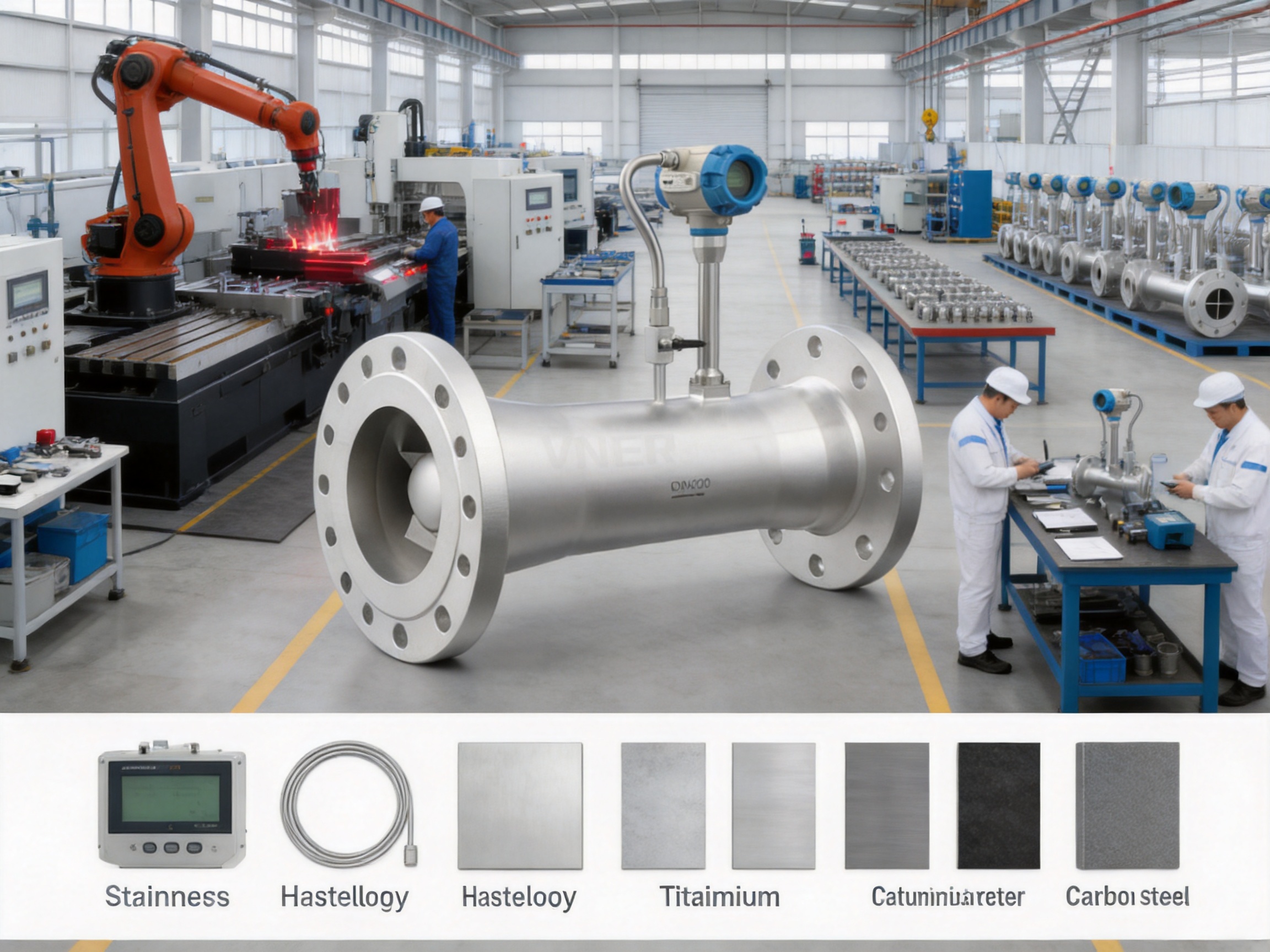
Manufacturing Strengths and Quality Approach
The manufacturer is a specialized industrial flowmeter producer based in Yangzhou, China. Since 2011, it has focused on flow measurement products covering electromagnetic, Coriolis, vortex, swirl, turbine, thermal mass, ultrasonic, and rotameter technologies. This broad product range gives the engineering team experience across liquid, gas, steam, and slurry applications.
The company operates approximately 23,000 square meters of modern facilities across three plants and has a technical team of more than 150 people. Its products have supported more than 2,000 engineering projects in over 30 countries. This project experience is important because flowmeter performance depends not only on the instrument itself but also on sizing, installation, process conditions, configuration, and commissioning.
In-House Calibration
In-house calibration is a key manufacturing strength. Calibration allows the relationship between flow conditions and instrument output to be verified before shipment. It also supports product consistency, traceability, and quality control across production batches.
For a compensated flowmeter, calibration and verification should cover more than the flow-frequency channel. The temperature and pressure measurement paths must also be checked, and the converter must correctly apply the configured calculation parameters. A coordinated internal process helps ensure that the complete instrument performs as an integrated system.
Engineering-Driven Selection
Industrial flowmeter selection cannot be reduced to choosing a nominal diameter from a price list. The manufacturer supports engineering-driven sizing and selection based on medium, density, temperature, pressure, flow range, pipe configuration, material requirements, and output requirements.
This approach is particularly valuable for steam and gas applications. A technically suitable meter may still perform poorly if it is incorrectly sized, installed near excessive turbulence, exposed to two-phase flow, or configured with inaccurate reference conditions. Application review before production reduces these risks.
Automated and Consistent Manufacturing
Increasingly automated manufacturing processes can improve repeatability in machining, assembly, welding, inspection, and testing. Automation does not eliminate the need for skilled technical personnel; instead, it supports consistent execution of defined processes while allowing engineers to focus on design verification, application analysis, and product improvement.
Consistency is especially important for flowmeter bodies, sensor installation, flange alignment, sealing surfaces, electrical connections, and converter configuration. Small variations in these areas can affect installation quality or long-term reliability. Controlled manufacturing processes help reduce variation from one instrument to another.
Quality Processes and Traceability
Certified quality processes, production records, inspection documentation, and traceability support the needs of EPC contractors, OEM partners, and industrial end users. Traceability is useful when instruments are installed in critical utility systems or when a plant requires documentation for maintenance, audits, or replacement planning.
The company’s project experience in oil and gas, petrochemical, polysilicon, power, water and wastewater, and general industrial applications contributes to a practical understanding of real operating environments. This field-oriented background helps connect product design with the challenges encountered during installation and service.
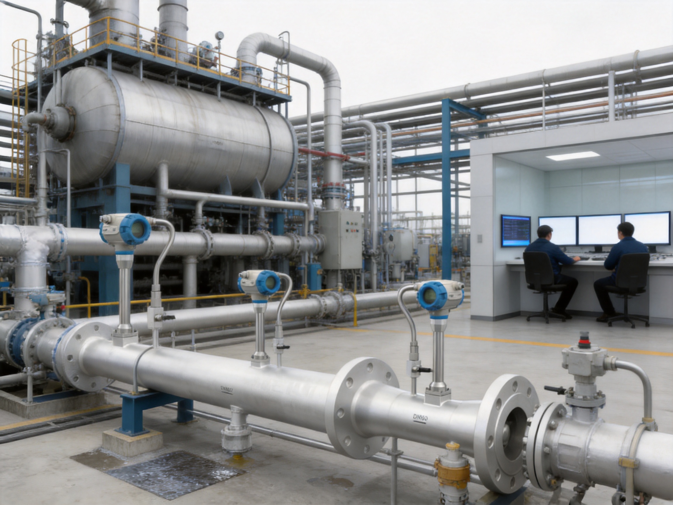
Material and Configuration Options
The standard body and flange options include carbon steel, SS304, and SS316L. Carbon steel may be suitable for many noncorrosive utility services when the pressure and temperature requirements are within the material rating. SS304 and SS316L provide increased corrosion resistance for a wider range of industrial environments.
Sensor wetted materials may be selected from SS304, SS316L, Hastelloy C, Hastelloy B, and titanium. The correct choice depends on the chemical composition of the medium, concentration, temperature, pressure, chloride content, pH, and possible contaminants. Material selection should be confirmed through process compatibility review rather than based only on general fluid names.
Piezoelectric sensing is the standard option and provides a compact method for detecting the flow-frequency signal. Capacitive sensing may be available for applications requiring an alternative sensing arrangement. The appropriate sensor type should be selected according to medium properties, temperature, vibration, signal conditions, and project requirements.
Process connections can be supplied according to GB, DIN, ANSI, or other standards on request. This flexibility helps the meter fit international project specifications and replacement requirements. Connection selection should include flange pressure class, gasket type, bolt materials, face condition, and thermal expansion considerations.
Energy Management and Cost Allocation
Energy management programs depend on reliable measurement at the points where energy is generated, transferred, and consumed. Steam and compressed gas are often distributed through complex networks with multiple users. Without sub-metering, plant managers may know the total utility production but not the consumption pattern of individual areas.
Compensated measurements from the SA80T-TP Series can be integrated into an energy dashboard or plant information system. Users can compare consumption by department, production line, building, or shift. Abnormal increases can be investigated through production records, valve positions, pressure trends, and maintenance data.
Cost allocation becomes more transparent when the quantity is measured using consistent reference conditions. This is particularly important when departments use different pressure levels or when a utility network experiences seasonal and production-related fluctuations. The meter can support a structured approach to internal billing and energy-performance evaluation.
Recommended Selection Information
Before selecting an SA80T-TP Series flowmeter, users should prepare a complete set of process data. The minimum information normally includes the measured medium, pipe size, normal flow rate, minimum flow rate, maximum flow rate, operating pressure, maximum pressure, operating temperature, maximum temperature, and required output units.
For gas service, gas composition, molecular weight, compressibility information, or the required gas standard should be provided where applicable. For steam, the user should identify whether the service is saturated or superheated and provide the expected pressure and temperature relationship.
Additional information should include flange standard, body material, sensor material, hazardous-area requirements, communication protocol, power supply, display requirements, straight-pipe availability, installation orientation, and the desired compensated variable. Supplying accurate data at the beginning of the project improves sizing quality and reduces later configuration changes.
Operational Best Practices
Keep the pipeline full and avoid locations where the medium can separate into liquid and gas phases.
Provide suitable upstream and downstream straight pipe according to the final application review.
Protect the meter from excessive mechanical vibration and unsupported pipe loads.
For steam, prevent condensate accumulation and verify the performance of steam traps and drainage points.
Confirm that the process temperature and pressure remain within the selected model’s limits.
Use the correct medium configuration, reference temperature, reference pressure, and engineering units.
Verify pressure and temperature readings during commissioning against calibrated reference instruments.
Review totalizer settings and communication mapping before using the meter for cost allocation.
Inspect wiring, cable glands, seals, and grounding connections according to the installation environment.
Schedule periodic verification based on service criticality, process conditions, and plant quality procedures.
Frequently Asked Questions
What is the main purpose of the SA80T-TP Series?
The main purpose is to measure flow while compensating for the effects of process temperature and pressure. It is intended especially for steam, compressed air, and industrial gas systems where operating volume alone does not provide a sufficiently representative quantity.
Does the meter directly measure mass flow?
The meter measures flow frequency and uses integrated temperature and pressure measurements to calculate density and compensated flow. The resulting mass flow is a calculated value rather than a direct Coriolis measurement. Its suitability depends on the medium, configuration, operating range, and required accuracy.
Can it measure both saturated and superheated steam?
Yes, the product is designed for saturated and superheated steam applications within the selected model’s temperature and pressure limits. The steam type and operating conditions must be correctly configured, and the installation must avoid excessive condensate and two-phase flow.
What outputs are available?
Primary outputs include 4–20 mA and pulse signals. HART and Modbus RTU communication are available as options. Outputs can be assigned to operating volumetric flow, compensated standard volume flow, mass flow, temperature, pressure, or other configured variables, depending on the converter arrangement.
What materials are available?
Body and flange materials include carbon steel, SS304, and SS316L. Sensor wetted materials may include SS304, SS316L, Hastelloy C, Hastelloy B, and titanium. The correct material should be selected according to the actual chemical and thermal conditions.
How accurate is the instrument?
Typical volumetric-flow accuracy is ±0.5 percent of rate for liquids and ±1.0 percent of rate for gases and steam under calibrated conditions. Final performance depends on sizing, installation, process stability, medium properties, calibration, and configuration.
What temperature range can the flowmeter handle?
The standard temperature capability is up to 250°C. Extended steam versions can support temperatures up to 400°C as an option, subject to model selection and engineering confirmation.
What pressure ratings are available?
Common pressure ratings include 1.6 MPa, 2.5 MPa, and 4.0 MPa. The correct rating must be selected according to the process design pressure, temperature, flange standard, and applicable safety requirements.
Is the meter suitable for compressed-air leak detection?
Yes. When configured for compressed air and installed at suitable monitoring points, it can provide standard volume or mass-related data for consumption analysis and leak detection. A leak survey normally requires multiple measurement points and comparison during production and nonproduction periods.
How does it compare with a Coriolis meter?
A Coriolis meter directly measures mass flow and may provide higher accuracy for certain high-value or custody-transfer applications. The SA80T-TP Series calculates mass flow from swirl frequency, temperature, and pressure. It may offer a more compact and economical solution for many steam and utility-gas applications, particularly in larger pipelines.
What information is needed for quotation and sizing?
Important information includes medium, pipe diameter, minimum, normal, and maximum flow, operating and maximum pressure, operating and maximum temperature, gas composition where applicable, steam type, connection standard, material requirements, output signals, communication requirements, and installation conditions.
Does the manufacturer provide customized solutions?
Customization may be available for materials, connection standards, sensor options, temperature capability, communication, and application-specific configuration. Each custom requirement should be reviewed against process conditions and manufacturing feasibility.
Conclusion
The SA80T-TP Series Temperature/Pressure Compensation Swirl Flowmeter is designed for industrial users who need more than basic volumetric flow measurement. By combining swirl flow sensing with integrated temperature and pressure measurement, it provides a practical method for calculating operating volume, standard volume, and mass flow for configured gases and steam.
Its key advantages include a no-moving-parts flow path, integrated compensation inputs, flexible materials, practical industrial outputs, optional digital communication, diagnostic functions, and compatibility with saturated steam, superheated steam, compressed air, nitrogen, fuel gas, and other suitable media. Compared with systems built from separate flow, pressure, temperature, and calculation instruments, it can simplify installation and reduce the number of components requiring maintenance.
The product is supported by a manufacturer with broad flowmeter expertise, in-house calibration, engineering-based selection, controlled manufacturing, certified quality processes, and international project experience. Modern facilities, a substantial technical team, multiple flow measurement technologies, and experience across process industries provide a strong foundation for customized industrial solutions.
For steam and gas networks, the best results come from treating the flowmeter as part of a complete measurement system. Accurate process data, suitable sizing, correct installation, reliable temperature and pressure measurement, appropriate configuration, and regular verification are all essential. When these factors are addressed, the SA80T-TP Series can contribute to more reliable process control, improved energy visibility, better utility management, and more defensible cost allocation.
References
1. International Organization for Standardization, Industrial Flow Measurement Principles and Practice.
2. International Organization for Standardization, Measurement of Fluid Flow in Closed Conduits.
3. International Electrotechnical Commission, Industrial-Process Measurement and Control Documentation Practices.
4. ASME, Steam Tables and Thermodynamic Properties of Water and Steam.
5. American Society of Mechanical Engineers, Flow Measurement Engineering Guidance.
6. Instrumentation and Automation Engineering Handbooks, Gas and Steam Flow Measurement Chapters.
7. Industrial Energy Management Guidelines for Steam and Compressed-Air Systems.
8. Manufacturer technical information for the SA80T-TP Series Temperature/Pressure Compensation Swirl Flowmeter.
Product: SA80T-TP Series Temperature/Pressure Compensation Swirl Flowmeter



Products
Contact Information
-

+86 18652789521
+86-0514-83633600 / 83633900 -

+86-0514-83633600 / 83633900
-

s@vner.com.cn
katherine@vner.com.cn -

No. 11 Xingye Road, Chenji Town Industrial Park, Yizheng, Yangzhou, China
