
 0
0
 EN
EN  English
 عربى
عربى Español
 русский
If you need any help, please feel free to contact us
Home / Author / Cai Shurong — After-Sales Project Coordinator / LWGY Series Liquid Turbine Flowmeter: High-Accuracy Measurement for Clean Liquid Applications
LWGY Series Liquid Turbine Flowmeter: High-Accuracy Measurement for Clean Liquid Applications
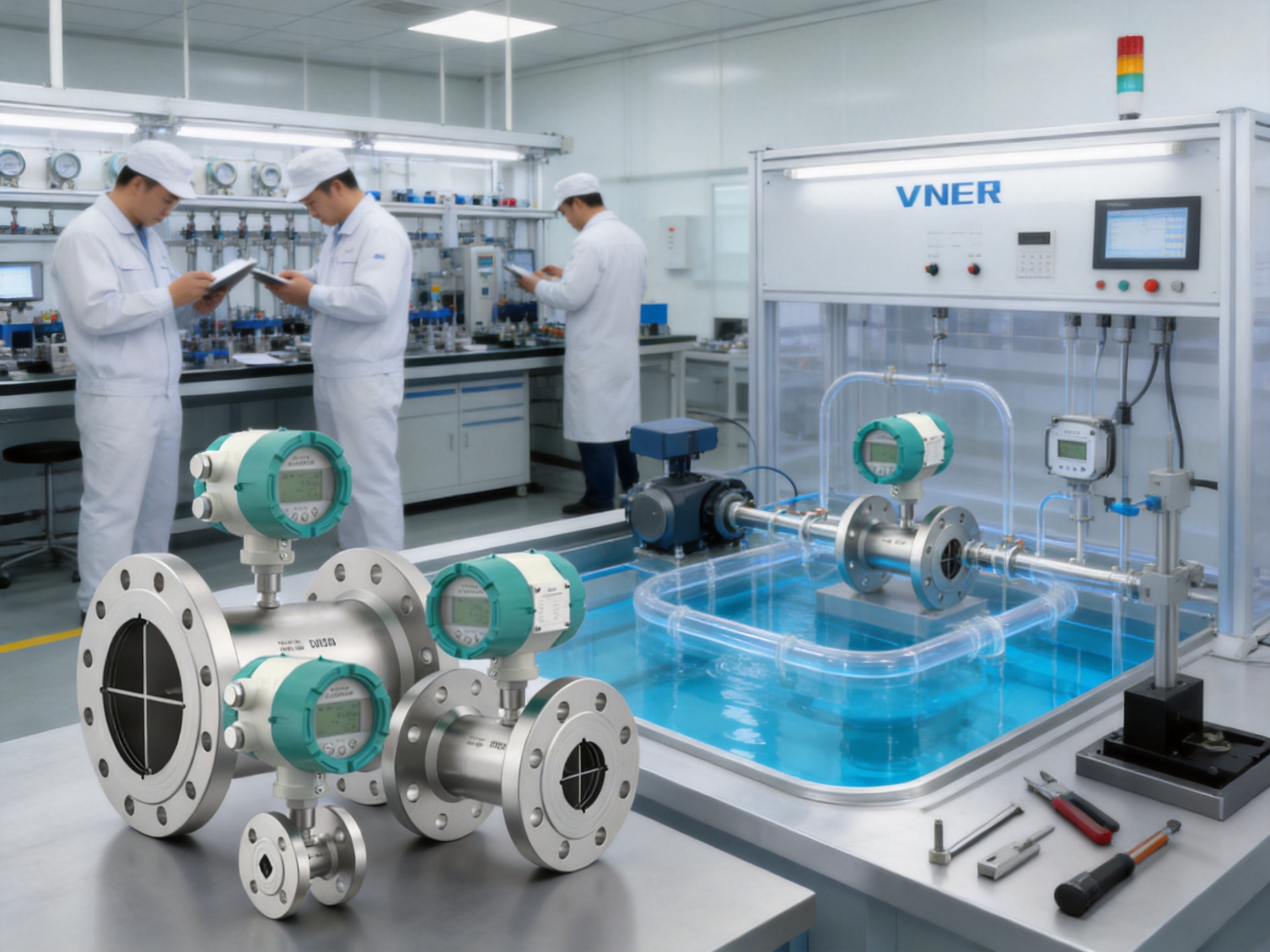
The LWGY Series Liquid Turbine Flowmeter is a compact, fast-response instrument developed for accurate volumetric measurement of clean, relatively low-viscosity liquids. By converting liquid velocity into turbine rotation and then into a high-resolution electrical pulse signal, the meter provides a practical solution for batching, dispensing, transfer monitoring, utility measurement and process control.
Turbine flowmeters remain widely used because they combine a straightforward measuring principle with strong repeatability, rapid response and a broad range of process connection options. The LWGY Series applies this established technology in a modern industrial instrument that can be configured for different pipe sizes, pressure classes, electrical interfaces, power supplies, output signals and communication requirements.
For users who need dependable flow measurement without the complexity or cost of some more advanced technologies, the LWGY provides an effective balance of accuracy, installation flexibility and operating economy. It is particularly suitable when the liquid is clean, filtration is available and the application requires a fast pulse output for batching or high-speed counting.
How the LWGY Liquid Turbine Flowmeter Works
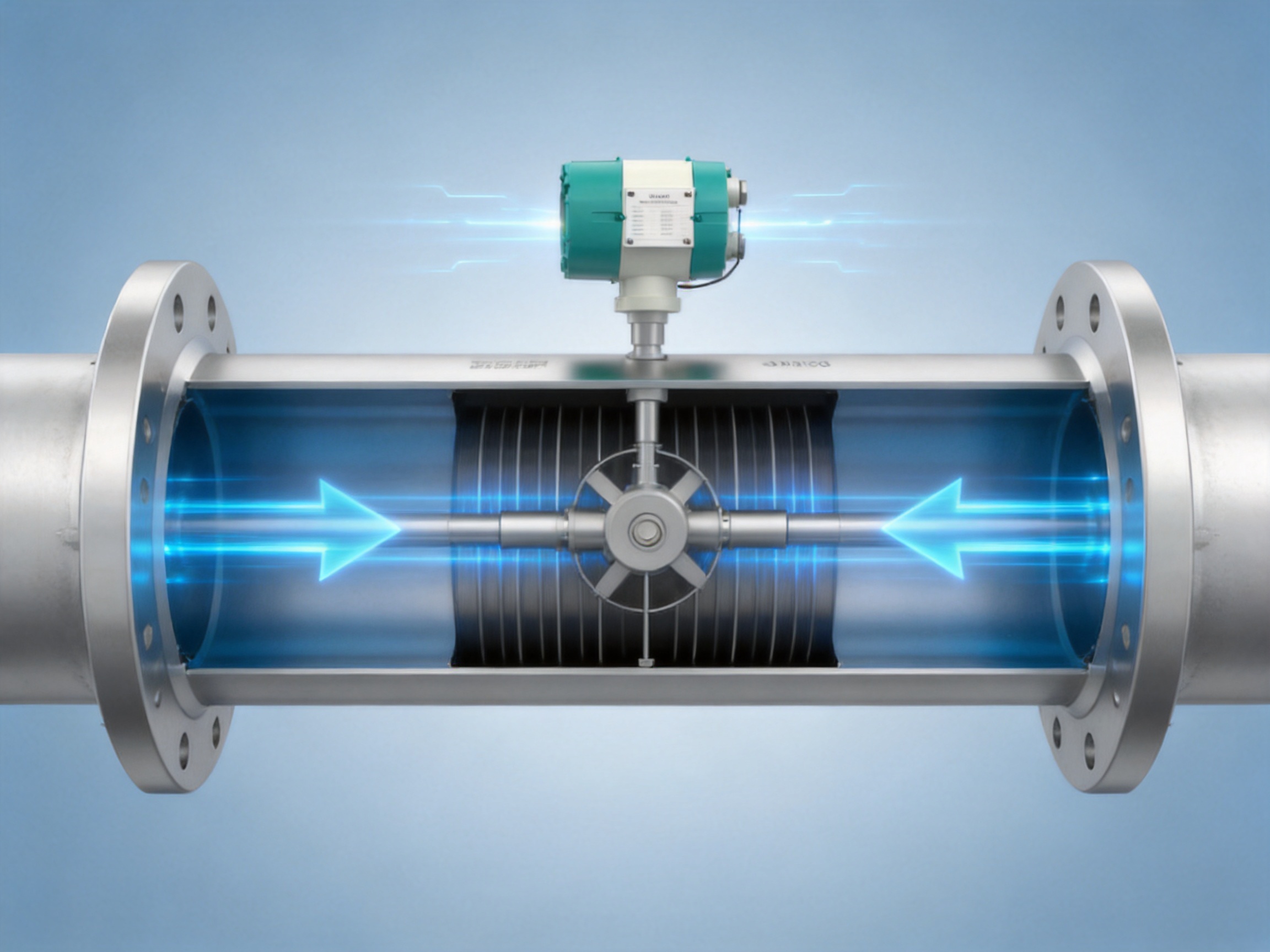
The LWGY Series operates according to the turbine measurement principle. The liquid enters the flowmeter body and passes through a flow straightener that helps organize the velocity profile. The controlled flow then moves across a turbine rotor installed in the measuring tube.
As liquid velocity increases, the rotor spins faster. As liquid velocity decreases, rotor speed also decreases. Within the specified operating range, the rotational speed of the rotor is proportional to the volumetric flow rate passing through the meter.
A pickup sensor detects the movement of the turbine blades. Each blade passage produces an electrical pulse, and the frequency of the pulse signal corresponds to the flow rate. The total number of pulses can also be used to calculate the accumulated volume, which makes the instrument particularly useful for batching and dispensing.
Depending on the selected configuration, the flowmeter can provide a pulse output, a 4-20 mA analog signal, or digital communication through Modbus RS-485 or optional HART communication. A local display and battery-powered version may also be selected for applications where independent field indication is required.
The measurement principle is mechanical and direct. Unlike differential-pressure meters, the flowmeter does not require a pressure transmitter and impulse tubing. Unlike electromagnetic meters, it does not require the liquid to have a minimum electrical conductivity. Unlike Coriolis meters, it generally offers a lighter and more economical solution for applications where direct mass measurement is not required.
Correct application selection remains important. Turbine meters perform best with clean liquids that do not contain large particles, fibers or excessive entrained gas. Proper upstream filtration and suitable installation conditions help protect the rotor and maintain measurement stability over time.
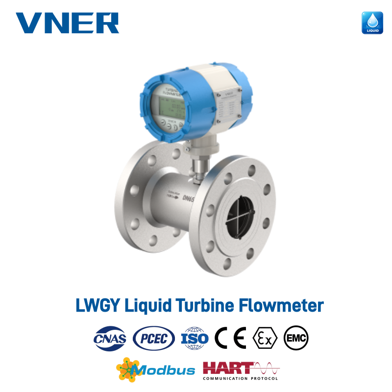
LWGY Series Liquid Turbine Flowmeter
Principal Advantages of the LWGY Series
High Accuracy and Repeatability
The LWGY Series can be supplied in accuracy classes of approximately ±0.2%, ±0.5% or ±1.0% of rate, depending on the selected model, calibration method, size and application conditions. Repeatability can reach approximately 0.05% to 0.20% of rate in suitable operating conditions.
High repeatability is valuable in applications where the same liquid is measured repeatedly, such as filling, chemical dosing or fuel transfer. Even when the absolute accuracy requirement is moderate, stable repeatability allows operators to identify process changes and maintain consistent production batches.
Actual performance depends on liquid viscosity, flow range, installation, upstream and downstream piping, temperature, pressure and the quality of calibration. For this reason, the meter should be selected and configured according to the complete process specification rather than by nominal pipe diameter alone.
Fast Response for Batching and Control
One of the most important benefits of turbine technology is its rapid response. The rotor reacts quickly to changes in liquid velocity, while the pickup sensor produces a high-frequency pulse signal suitable for fast counting and control.
This characteristic is useful in short-batch dosing, filling machines, blending skids and automated transfer systems. A controller can count pulses to determine the delivered volume and close a valve or stop a pump when the target quantity has been reached.
Compared with technologies that use longer signal filtering or complex internal calculations, the LWGY can provide a direct and responsive indication of changing flow. This helps reduce control delay in systems where the timing of valve closure or pump adjustment affects final batch accuracy.
Compact and Lightweight Construction
The flowmeter uses a compact body and a relatively simple internal structure. Its lightweight design makes it convenient for installation on skids, packaged equipment, branch lines and confined piping systems where a larger instrument would be difficult to support.
Compact construction can also reduce the need for special structural reinforcement. This is advantageous when the flowmeter is installed in a mobile filling system, a modular chemical unit or a prefabricated process package.
Although the instrument is compact, the body can be configured for a variety of pressure ratings and connection standards. Available options include flanged, threaded, hygienic and wafer-type connections, depending on the model and process requirements.
Wide Size and Connection Selection
The nominal diameter range extends approximately from DN4 to DN200, corresponding to about 1/8 inch to 8 inches. This range allows the same basic measurement technology to be applied to small dosing lines, medium-sized utility circuits and larger liquid transfer systems.
Connection standards may include DIN, ANSI/ASME and JIS designs. Pressure options can include PN16 and PN25, ANSI Class 150 and Class 300, and JIS 10K or 20K configurations. These options allow the instrument to be integrated into local piping standards and international equipment packages.
When selecting the connection, engineers should verify flange dimensions, face-to-face length, pressure-temperature rating, gasket requirements, pipe schedule and material compatibility. A correctly matched connection simplifies installation and helps prevent mechanical stress on the meter body.
Flexible Electrical Configuration
The LWGY Series supports several power supply options, including 24 V DC, 220 V AC and a built-in 3.6 V battery for selected local indicator versions. This flexibility allows the instrument to be used in control cabinets, field installations and stand-alone measurement points.
Pulse output is suitable for totalizers, batch controllers, counters and programmable logic controllers. The 4-20 mA output is convenient for distributed control systems, remote displays and supervisory monitoring. Modbus RS-485 supports digital integration with PLC, DCS and SCADA systems, while HART can be specified where intelligent field-device communication is required.
Electrical interfaces may be provided with M20 × 1.5 or 1/2-inch NPT cable entries. The enclosure can offer IP65 protection for standard applications, with explosion-proof Ex d versions available for selected hazardous-area requirements.
Technical Specification Overview
| Item | Typical Specification |
|---|---|
| Measuring principle | Turbine rotor speed proportional to liquid velocity |
| Measured media | Clean liquids with low solids content |
| Accuracy classes | Approximately ±0.2%, ±0.5% or ±1.0% of rate, configuration-dependent |
| Repeatability | Approximately 0.05% to 0.20% of rate |
| Nominal diameters | DN4 to DN200, approximately 1/8 inch to 8 inches |
| Typical velocity range | Approximately 0.5 to 5 m/s, depending on size and medium |
| Turndown ratio | Up to approximately 1:20 on medium and large sizes; up to approximately 1:10 on small sizes |
| Process connections | Flanged, hygienic, threaded and wafer-type options |
| Connection standards | DIN, ANSI/ASME and JIS |
| Medium temperature | Approximately -20°C to +150°C, according to model and materials |
| Pressure ratings | PN16, PN25, ANSI 150, ANSI 300, JIS 10K and JIS 20K options |
| Body materials | Stainless steel 304 or 316 |
| Rotor and internal materials | 2Cr13, CD4MCu and other specified wear- or corrosion-resistant alloys |
| Protection class | IP65 standard configuration |
| Explosion protection | Ex d versions available for selected configurations |
| Power supplies | 24 V DC, 220 V AC or 3.6 V built-in battery option |
| Output signals | Pulse and 4-20 mA |
| Communication | Modbus RS-485 and optional HART |
| Electrical interfaces | M20 × 1.5 or 1/2-inch NPT |
The values above represent typical configuration ranges. The final specification should be confirmed against the selected size, process liquid, material combination, hazardous-area classification, calibration requirement and applicable market certification.
Materials and Mechanical Design
The standard meter body can be manufactured from stainless steel 304 or stainless steel 316. Stainless steel 304 is suitable for many general-purpose water, oil and industrial liquid services. Stainless steel 316 provides improved resistance in applications involving more aggressive chemical environments or chloride exposure, subject to a detailed compatibility review.
The rotor and internal components may use 2Cr13, CD4MCu or other specified alloys selected for wear resistance, corrosion resistance and mechanical stability. The choice of internal material affects service life, start-up behavior and compatibility with the measured liquid.
The flow straightener is important because it conditions the liquid before it reaches the rotor. A more uniform velocity profile helps the rotor respond consistently and reduces the influence of moderate upstream flow disturbances. The flowmeter should still be installed with appropriate straight pipe lengths and away from severe swirl, partially open valves, pumps or elbows whenever possible.
The mechanical design is intentionally uncomplicated. Fewer electronic measurement components are exposed to the process liquid, and the primary sensing action is based on rotor movement and pulse detection. This can simplify troubleshooting compared with instruments that depend on multiple pressure, temperature or excitation circuits.
At the same time, the rotor is a precision moving component and should not be treated as immune to contamination. Abrasive solids, fibrous material, sticky deposits and heavy fouling can affect rotor balance or prevent free movement. Upstream filtration is therefore an important part of a reliable turbine flow measurement system.
Comparison with Other Flowmeter Technologies
Comparison with Electromagnetic Flowmeters
Electromagnetic flowmeters are highly effective for conductive liquids, wastewater, slurries and liquids containing suspended solids. They have no moving parts in the flow path and can offer excellent long-term stability in demanding services.
The LWGY has a different strength. It can measure many clean, low-conductivity liquids that are not suitable for electromagnetic measurement, including certain hydrocarbons, refined products and organic solvents. It also tends to have a smaller and lighter structure for the same nominal line size and can deliver a direct high-frequency pulse signal for batching.
Where the liquid is conductive and contains solids, an electromagnetic meter may be the better choice. Where the liquid is clean, relatively low in viscosity and the application emphasizes fast volumetric measurement, the turbine meter can offer a more economical and responsive solution.
Comparison with Coriolis Mass Flowmeters
Coriolis flowmeters measure mass flow directly and may also provide density and temperature information. They are well suited to applications requiring highly accurate mass measurement, changing density compensation or advanced process diagnostics.
However, Coriolis meters are generally more complex and may have higher purchase costs, greater weight and larger pressure loss in some size ranges. The LWGY measures volumetric flow rather than mass flow, but it can be a better choice when the liquid density is stable and the required measurement is volume-based.
For filling, transfer and utility flow monitoring, the pulse output of a turbine meter may provide all the information required. In this situation, selecting a Coriolis meter could introduce capability that the process does not need.
Comparison with Vortex Flowmeters
Vortex flowmeters are commonly used for gases, steam and some liquids. They measure the frequency of vortices generated behind a bluff body and can provide a broad process measurement solution.
The LWGY is especially advantageous when the application involves clean liquid batching, small pipe sizes, rapid pulse counting or a compact mechanical arrangement. Turbine meters can also provide strong repeatability in stable liquid services.
Vortex meters may be more suitable for mixed utility platforms that measure both gas and liquid or for applications where a moving rotor is undesirable. The choice should be based on the medium, velocity range, pressure loss, required output and maintenance conditions.
Comparison with Positive Displacement Meters
Positive displacement meters measure liquid by repeatedly capturing and releasing known volumes. They can provide excellent low-flow performance and are widely used for viscous liquids and custody-transfer applications.
The LWGY generally offers a lighter and more compact alternative for clean, low-viscosity liquids at moderate or higher flow velocities. It may also provide lower mechanical complexity than some positive displacement designs. Positive displacement meters may be preferable when the liquid is viscous or when very low flow measurement is the primary requirement.
Comparison with Variable-Area Rotameters
Metal tube rotameters provide a simple local indication and can operate without complex external control systems. They are useful for visual monitoring and low-cost flow indication.
The LWGY offers stronger electronic integration. Its pulse, 4-20 mA and digital communication options make it more appropriate for automated batching, PLC control, remote monitoring and totalized measurement.
Manufacturing Strengths and Quality Approach
The performance of a turbine flowmeter depends not only on its design concept but also on the precision and consistency of manufacturing. Rotor geometry, shaft alignment, sensor positioning, body dimensions, surface finish and calibration quality all influence measurement results.
Jiangsu VNER Electronic Technology Co., Ltd. is an industrial flowmeter manufacturer based in Yangzhou, China. Established in 2011, the company develops and manufactures electromagnetic, Coriolis, vortex, swirl, turbine, thermal mass, ultrasonic and metal tube rotameter products for liquid, gas and slurry measurement.
The company operates modern facilities covering approximately 23,000 square meters across three plants and maintains a technical team of more than 150 people. Its experience includes more than 2,000 engineering projects delivered across over 30 countries.
This engineering background supports the production of the LWGY Series in several important ways. First, the company can draw on experience across different flow measurement principles. This makes it easier to identify when a turbine meter is appropriate and when a different technology would provide a more reliable result.
Second, experience with different industries helps the engineering team understand practical installation issues. Pipe configuration, pump operation, liquid cleanliness, pressure fluctuations, control-system requirements and hazardous-area conditions must all be considered during selection.
Third, a broad product portfolio supports OEM and packaged-equipment projects. Customers may require several different flowmeter technologies in one plant. Working with a single experienced supplier can simplify technical communication, documentation, customization and spare-parts management.
In-House Calibration and Traceability
Calibration is one of the most important manufacturing processes for a turbine flowmeter. The relationship between pulse frequency and flow rate must be established through controlled testing. Calibration data can then be used to configure the transmitter, generate meter factors and provide product documentation.
In-house calibration capabilities help maintain better control over the production process. They also support traceability from the finished instrument back to test conditions, configuration records and inspection results.
For customers, traceable calibration can be especially valuable in batching, chemical dosing, fuel transfer and quality-controlled production. It provides a documented basis for evaluating meter performance and supports periodic verification during the service life of the instrument.
Automated and Controlled Production
Increasingly automated manufacturing can improve consistency in assembly, inspection and data recording. Automated or semi-automated processes are particularly useful when a product family includes many sizes, materials, connection standards and electronics configurations.
Controlled production helps reduce variation in rotor installation, sensor alignment, terminal assembly and enclosure preparation. It also supports repeatable manufacturing for OEM orders, where instruments must match a defined specification across multiple production batches.
Automation does not replace engineering judgment. The most effective production approach combines standardized processes with experienced technical personnel who can review application requirements, investigate abnormal test results and recommend appropriate configurations.
Engineering-Driven Product Selection
A flowmeter should not be selected solely by matching the meter size to the pipe size. The actual liquid flow range, viscosity, density, temperature, pressure, vapor pressure, solids content and required accuracy must be evaluated.
The supplier’s engineering team can help determine whether the expected operating velocity falls within the stable range of the selected turbine meter. It can also identify the need for filtration, upstream straightening, special materials, a remote display, hazardous-area protection or a different measurement technology.
This engineering-driven approach is an important advantage over purely catalog-based purchasing. It reduces the risk of selecting a meter that is technically compatible with the pipe but unsuitable for the actual process conditions.
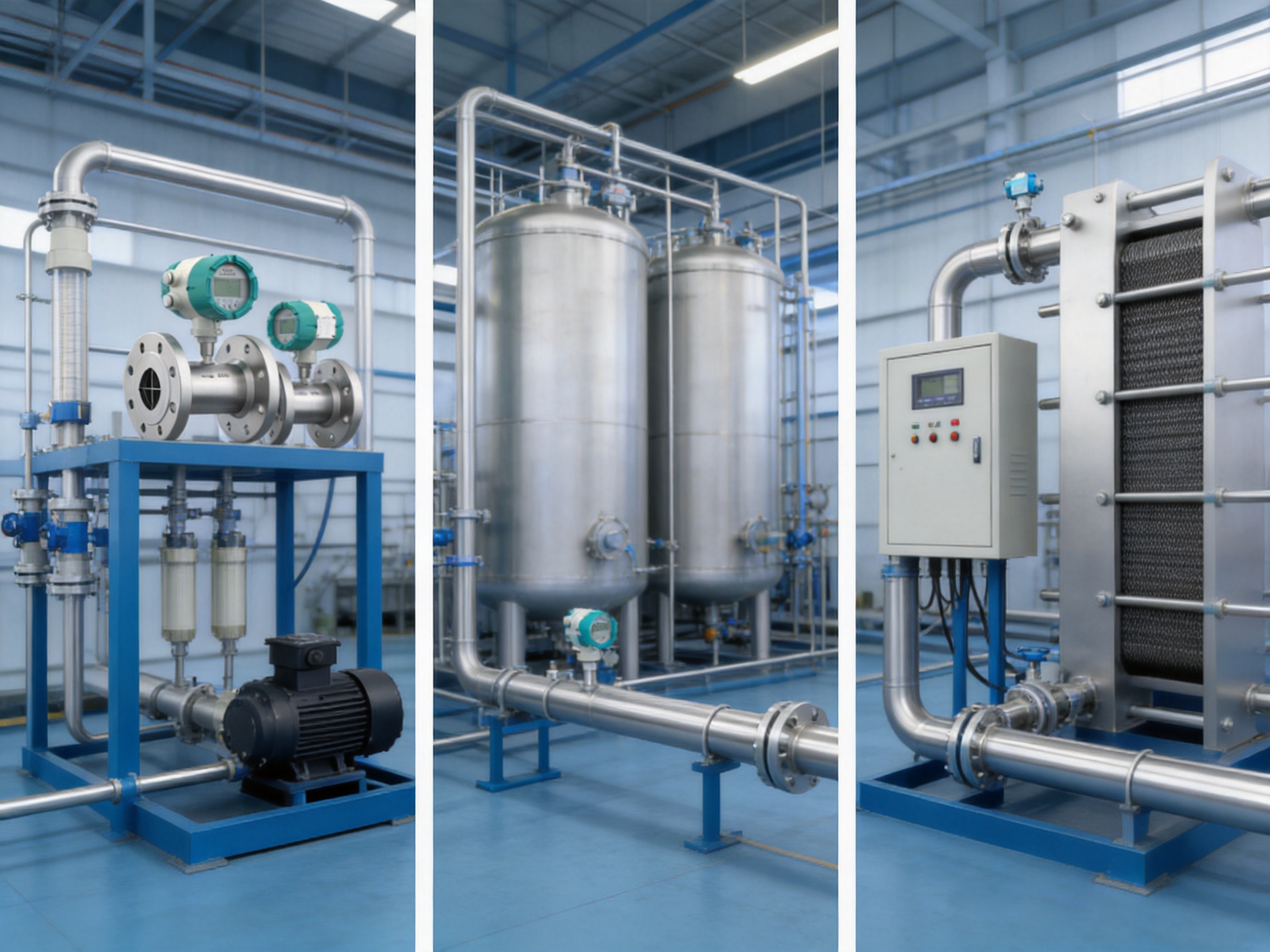
Applications in Industrial and Commercial Systems
Solvent Batch Dosing
In a chemical blending skid, an LWGY meter installed on a DN25 to DN50 solvent line can provide a fast pulse signal to a batch controller. The controller counts pulses and uses the accumulated value to determine the delivered volume.
Because solvents may contain impurities from storage tanks, upstream filtration should be considered. The filter should be selected to protect the rotor without creating excessive pressure loss or frequent blockage. The material of the filter, gaskets and meter body should also be checked for chemical compatibility.
The compact form of the meter is useful in skid systems where several dosing lines are installed close together. A 4-20 mA output can be added for continuous monitoring, while pulse output is used for the actual batch total.
Cooling Water Monitoring
On DN40 to DN80 cooling-water lines, the LWGY can monitor circulation flow to compressors, heat exchangers, molding machines or other industrial equipment. The signal can be sent to a PLC for flow verification, alarm generation and basic energy-balance calculations.
Cooling-water circuits should be evaluated for suspended solids, corrosion products and biological growth. If the water is well controlled and filtered, the turbine meter can provide stable volumetric measurement. If the circuit contains substantial solids or persistent fouling, an electromagnetic meter may be more suitable.
The fast response of the turbine meter allows the control system to detect a loss of circulation quickly. This can help protect heat-generating equipment from insufficient cooling flow.
Light Oil Transfer and Filling
Clean lubrication oils, diesel, kerosene and other refined products can be suitable for turbine measurement when their viscosity remains within the operating limits of the selected meter.
In filling or packaging lines, pulse counting can be used to control a target volume. Repeatable performance helps maintain consistent quantities across multiple filling heads, provided that valve response, pump pulsation, air elimination and liquid temperature are also controlled.
For fuel or solvent service, users should verify the electrical classification, enclosure requirements and bonding or grounding provisions. Ex d versions may be available for selected hazardous-area applications, subject to the relevant certification and installation requirements.
HVAC Water Loop Sub-Metering
Turbine meters can be installed on branch chilled-water or hot-water circuits to provide zone-level volumetric flow data. When flow data is combined with supply and return temperature measurements, a heat calculator can estimate thermal energy consumption.
This application requires good water quality and a properly maintained system. Air bubbles, debris and unstable flow can reduce measurement quality. Installation should also account for pumps, control valves and balancing devices that may create excessive turbulence.
Where the meter is used for internal monitoring rather than legal trade measurement, the LWGY can provide a practical and economical way to improve visibility of building or process energy use.
Water, Alcohols and Thin Syrups
The meter can be used for process water, utility water, alcohol-based liquids and certain thin syrups when the viscosity remains within the turbine’s acceptable range. Increasing viscosity can change rotor behavior and affect the calibration relationship, particularly at lower flow rates.
Food and beverage applications require careful attention to hygienic design, cleanability, material compatibility and applicable regulatory requirements. Hygienic connections and appropriate wetted materials may be available for selected configurations.
Installation Guidelines for Reliable Performance
Confirm the Liquid Is Suitable
The first installation step is to confirm that the liquid is clean enough for a moving-rotor meter. Large particles, fibers, crystallizing material and sticky deposits can cause wear or restrict the rotor.
Users should document the liquid’s viscosity, density, temperature, pressure, conductivity, solids content and vapor pressure. For chemical products, compatibility with stainless steel, rotor alloys, seals and gaskets should be checked before ordering.
Use Suitable Filtration
A strainer or filter installed upstream can protect the turbine rotor from particles. The filter rating should be selected according to the rotor design and the cleanliness of the process. A filter that is too fine may create excessive pressure loss or require frequent maintenance.
The filter should be installed where it can be inspected and cleaned safely. Differential-pressure monitoring across the filter can help identify blockage before it reduces the available flow or causes pump problems.
Provide Stable Flow Conditions
Although the internal flow straightener improves the velocity profile, the meter should not be installed directly after a pump discharge, control valve, sharp elbow, reducer or tee if avoidable. Such components can generate swirl, pulsation or asymmetric velocity profiles.
Adequate straight pipe upstream and downstream helps the rotor operate under more predictable conditions. The exact requirements depend on the pipe arrangement, meter design and manufacturer’s installation instructions.
The meter should be installed so that the pipe remains full during normal operation. A partially filled line, falling pipe or location near a high point can introduce air and cause unstable readings.
Control Gas and Air Entrapment
Entrained air or gas bubbles can cause the rotor to accelerate irregularly and may lead to over-reading or unstable pulse output. Air release devices, suitable piping slopes and correct pump operation can help reduce this risk.
For liquids that are close to their vapor pressure, the system should be designed to avoid flashing and cavitation. Maintaining adequate backpressure downstream of the meter may be necessary.
Observe Flow Direction and Mechanical Support
The arrow on the flowmeter body must match the actual process flow direction. Flanges should be aligned without forcing the meter into position, and pipe supports should prevent excessive mechanical load on the meter.
Threaded and wafer-type installations require particular care during tightening. Over-tightening can damage threads, seals or the body. Flanged installations should use suitable gaskets and a controlled bolt-tightening sequence.
Plan the Electrical Installation
Cable entries should be sealed correctly to maintain enclosure protection. Signal cables should be routed away from strong sources of electromagnetic interference where practical. Shielding and grounding should follow the transmitter and control-system requirements.
Before energizing the instrument, the installer should confirm the power supply, output wiring, pulse scaling, alarm settings and communication parameters. For hazardous-area versions, all installation work must comply with the applicable Ex requirements.
Maintenance and Operating Practices
The LWGY Series has a simple mechanical structure and can require relatively little maintenance when used with clean, filtered liquids. A preventive maintenance plan should nevertheless include inspection of the filter, verification of signal stability and periodic comparison with a reference measurement where required.
Changes in pulse stability, increased pressure loss or unexpected low-flow behavior may indicate contamination, rotor wear, bearing problems, air entrainment or an upstream process change.
When maintenance is required, the meter should be isolated, depressurized and drained according to the site’s safety procedures. The rotor and internal components should be inspected for deposits, corrosion, mechanical damage and free movement.
Cleaning methods must be compatible with the body, rotor, seals and process residue. Abrasive tools or aggressive chemicals can damage precision surfaces. Replacement parts should match the original material and design specification.
Periodic verification may be performed by comparing the meter with a calibrated reference meter, a gravimetric system, a volumetric prover or another approved method. The appropriate interval depends on the criticality of the application, process cleanliness, operating hours and quality-system requirements.
Configuration Options for Different Projects
The LWGY Series can be adapted to different project requirements through a combination of mechanical and electronic options. Engineers may specify the nominal diameter, body material, rotor material, connection standard, pressure rating, temperature range and display arrangement.
For control-system integration, the output may include pulse, 4-20 mA, Modbus RS-485 or HART. A high-resolution pulse output, reaching approximately 3 to 4 kHz in suitable configurations, supports precise batching and high-speed counting.
A local battery-powered indicator can be useful where mains power is unavailable or where the instrument is installed as an independent field totalizer. A 24 V DC version is convenient for most industrial control panels, while 220 V AC can be selected where the existing installation standard requires it.
IP65 protection is suitable for many indoor and sheltered outdoor installations. If the meter is exposed to weather, washdown or hazardous conditions, the enclosure, cable glands, display and certification should be reviewed as a complete system.
For international projects, CE, ATEX and other certification requirements should be confirmed according to the exact model and destination market. Certification availability can vary by product configuration and should not be assumed solely from the product family name.
Engineering Selection Checklist
| Selection Item | Information to Confirm |
|---|---|
| Liquid identity | Composition, cleanliness, solids, fibers and corrosiveness |
| Viscosity | Normal, minimum and maximum operating viscosity |
| Density | Normal operating density and expected variation |
| Flow range | Minimum, normal, maximum and occasional peak flow |
| Pipe size | Nominal diameter, schedule and internal diameter |
| Temperature | Normal, minimum and maximum process temperature |
| Pressure | Operating pressure, design pressure and pressure transients |
| Connection | Flanged, threaded, wafer or hygienic connection standard |
| Accuracy | Required accuracy, repeatability and calibration standard |
| Output | Pulse, 4-20 mA, Modbus RS-485, HART or combined outputs |
| Power | 24 V DC, 220 V AC or battery-powered local indication |
| Environment | Indoor, outdoor, washdown, hazardous area or corrosive atmosphere |
| Installation | Available straight pipe, pipe orientation and access for maintenance |
| Documentation | Calibration certificate, material certificate, inspection records and manuals |
Providing complete information at the quotation stage improves the chance of receiving a correctly sized and configured instrument. It also reduces later changes to piping, wiring, supports and control logic.
Why Manufacturing Experience Matters to Buyers
Purchasing a flowmeter is not simply a matter of comparing a list price. The cost of an incorrect selection can include installation changes, production interruptions, inaccurate batches, repeated calibration work and unplanned maintenance.
An experienced manufacturer can contribute value before production begins by reviewing the application and identifying potential risks. During manufacturing, controlled assembly and calibration help establish consistent performance. After delivery, technical documentation and application support help the end user install and operate the instrument correctly.
For OEM customers, manufacturing consistency is particularly important. Equipment builders may need dozens or hundreds of meters with identical electrical interfaces, pulse scaling, connection dimensions and documentation. A structured production system makes repeat orders easier to manage.
For EPC contractors, documentation and international project experience can simplify approval processes. Material information, calibration data, dimensional drawings and electrical specifications may be required for procurement, inspection and commissioning.
For end users, long-term reliability is supported by product traceability, available replacement components, clear maintenance instructions and a supplier capable of supporting more than one measurement technology when process conditions change.
Limitations and Correct Application Boundaries
No flowmeter is suitable for every medium. The LWGY Series is intended primarily for clean, non-fouling liquids. It should not be selected automatically for slurries, wastewater with heavy solids, liquids containing long fibers or highly viscous fluids without a detailed technical review.
Electromagnetic flowmeters are often more appropriate for conductive slurries and dirty liquids. Coriolis flowmeters may be better for direct mass measurement, changing density or high-value chemical dosing. Positive displacement meters may provide better performance for viscous liquids or very low flow rates.
Turbine meters also require attention to velocity range. Operating continuously below the recommended minimum can reduce accuracy and increase sensitivity to friction, bearing behavior and installation effects. Operating above the maximum can increase wear and pressure loss.
Changes in viscosity caused by temperature variation can influence the meter factor. If a liquid becomes significantly more viscous during cold start-up, the meter may require application-specific calibration or temperature management.
These limitations do not reduce the value of the LWGY. Instead, they define the conditions under which its advantages are strongest: clean liquid service, stable or known viscosity, appropriate velocity, controlled installation and a requirement for fast, repeatable volumetric measurement.
Q&A
What type of liquid can the LWGY Series measure?
The meter is designed for clean, relatively low-viscosity liquids with low solids content. Examples may include water, light oils, diesel, kerosene, solvents, alcohols and certain thin syrups, provided that the viscosity, temperature, pressure and material compatibility are suitable.
Can the LWGY measure slurry or wastewater?
It is generally not the preferred choice for liquids with high solids content, fibrous material or severe fouling. Electromagnetic flowmeters are often more suitable for conductive slurries and dirty water because they have no moving rotor in the flow path.
What is the main output of a turbine flowmeter?
The primary signal is normally a pulse output generated by the pickup sensor as the rotor blades pass. The pulse frequency represents instantaneous flow, while the total number of pulses represents accumulated volume. Selected versions also provide 4-20 mA, Modbus RS-485 or HART communication.
Is a turbine flowmeter suitable for batching?
Yes. Its fast response and high-resolution pulse output make it suitable for batch dosing, filling and dispensing. The batch controller must be configured with the correct meter factor and should account for valve closing time, pump behavior and any liquid retained in the downstream pipe.
Does the meter require a filter?
Filtration is strongly recommended when the liquid may contain particles that could damage or restrict the rotor. The filter size and rating should be chosen according to the liquid, flow rate, allowable pressure loss and meter design.
What pipe sizes are available?
Typical nominal diameters range from approximately DN4 to DN200, or about 1/8 inch to 8 inches. Availability depends on the specific body design, connection type, pressure rating and project requirements.
What materials are used for the body and rotor?
Body options include stainless steel 304 and 316. Rotor and internal components may use 2Cr13, CD4MCu or other specified alloys. The correct choice depends on liquid chemistry, temperature, pressure and expected wear conditions.
Can the flowmeter be used in a hazardous area?
Explosion-proof Ex d versions are available for selected configurations. The exact certification, electrical parameters, cable entries and installation method must be confirmed for the applicable hazardous-area classification and market.
How should the meter be installed?
The meter should be installed in the correct flow direction on a completely filled pipe, with suitable straight pipe sections and minimal upstream turbulence. It should be protected from excessive vibration, mechanical stress, air entrainment and particles.
What power supplies are available?
Typical options include 24 V DC, 220 V AC and a 3.6 V built-in battery for selected local indicator versions. The choice depends on the site power system and whether remote signal transmission is required.
How often should the meter be calibrated?
Calibration intervals depend on application criticality, operating conditions, process cleanliness, quality-system requirements and site regulations. Critical batching or transfer applications may require more frequent verification than general utility monitoring.
What information should be submitted for sizing?
Important information includes liquid name and composition, minimum and maximum flow, normal flow, viscosity, density, temperature, pressure, pipe size, connection standard, required accuracy, output signal, hazardous-area classification and installation conditions.
Can the meter replace an electromagnetic or Coriolis flowmeter?
It may replace those technologies when the liquid is clean, the viscosity is appropriate and volumetric flow measurement is sufficient. It should not replace them automatically in slurry service, highly conductive dirty-liquid service or applications requiring direct mass measurement.
Conclusion
The LWGY Series Liquid Turbine Flowmeter provides an efficient solution for clean-liquid measurement where accuracy, repeatability, rapid response and compact installation are important. Its turbine rotor converts liquid velocity into a reliable pulse signal, while optional 4-20 mA and digital communication support integration with modern control systems.
Its advantages are strongest in batching, dispensing, light-oil transfer, solvent dosing, cooling-water monitoring and selected HVAC or process-water applications. A range of sizes, materials, process connections, pressure ratings, power supplies and output options allows the product to be adapted to different industrial requirements.
Compared with electromagnetic, Coriolis, vortex, positive displacement and variable-area technologies, the LWGY occupies a practical position for clean, low-viscosity liquids requiring economical and responsive volumetric measurement. Correct filtration, proper installation and suitable application selection are essential for achieving dependable service.
Supported by in-house calibration, controlled manufacturing, engineering-driven sizing, international project experience and a broad portfolio of flow measurement technologies, Jiangsu VNER Electronic Technology Co., Ltd. is positioned to supply the LWGY Series for standard instruments, OEM equipment, EPC projects and customized industrial applications.
References
1. International Organization for Standardization, Measurement of Fluid Flow in Closed Conduits: General Principles and Flowmeter Selection.
2. International Organization for Standardization, Measurement of Fluid Flow in Closed Conduits: Velocity-Area Methods and Installation Considerations.
3. International Electrotechnical Commission, Degrees of Protection Provided by Enclosures for Electrical Equipment.
4. International Electrotechnical Commission, Electrical Apparatus for Explosive Gas Atmospheres and Explosion-Protected Equipment Requirements.
5. American Society of Mechanical Engineers, Measurement of Fluid Flow in Closed Conduits.
6. Instrumentation engineering practices for turbine flowmeter sizing, installation, calibration and maintenance.
7. Manufacturer technical documentation for LWGY Series Liquid Turbine Flowmeter configurations and application guidance.
Product: LWGY Series Liquid Turbine Flowmeter


We offer all our products and services at international standards.
Products
Contact Information
-

+86-18652789521
+86-18052582295
+86-0514-83633600 / 83633900 -

+86-0514-83633600 / 83633900
-

shawn@vnerflow.com
info@vnerflow.com -

No. 11 Xingye Road, Chenji Town Industrial Park, Yizheng, Yangzhou, China
