
 0
0
 EN
EN  English
 عربى
عربى Español
 русский
If you need any help, please feel free to contact us
Home / Author / Cai Shurong — After-Sales Project Coordinator / ST51 Series Thermal Mass Flowmeter: Direct Gas Mass Measurement for Modern Industrial Systems
ST51 Series Thermal Mass Flowmeter: Direct Gas Mass Measurement for Modern Industrial Systems
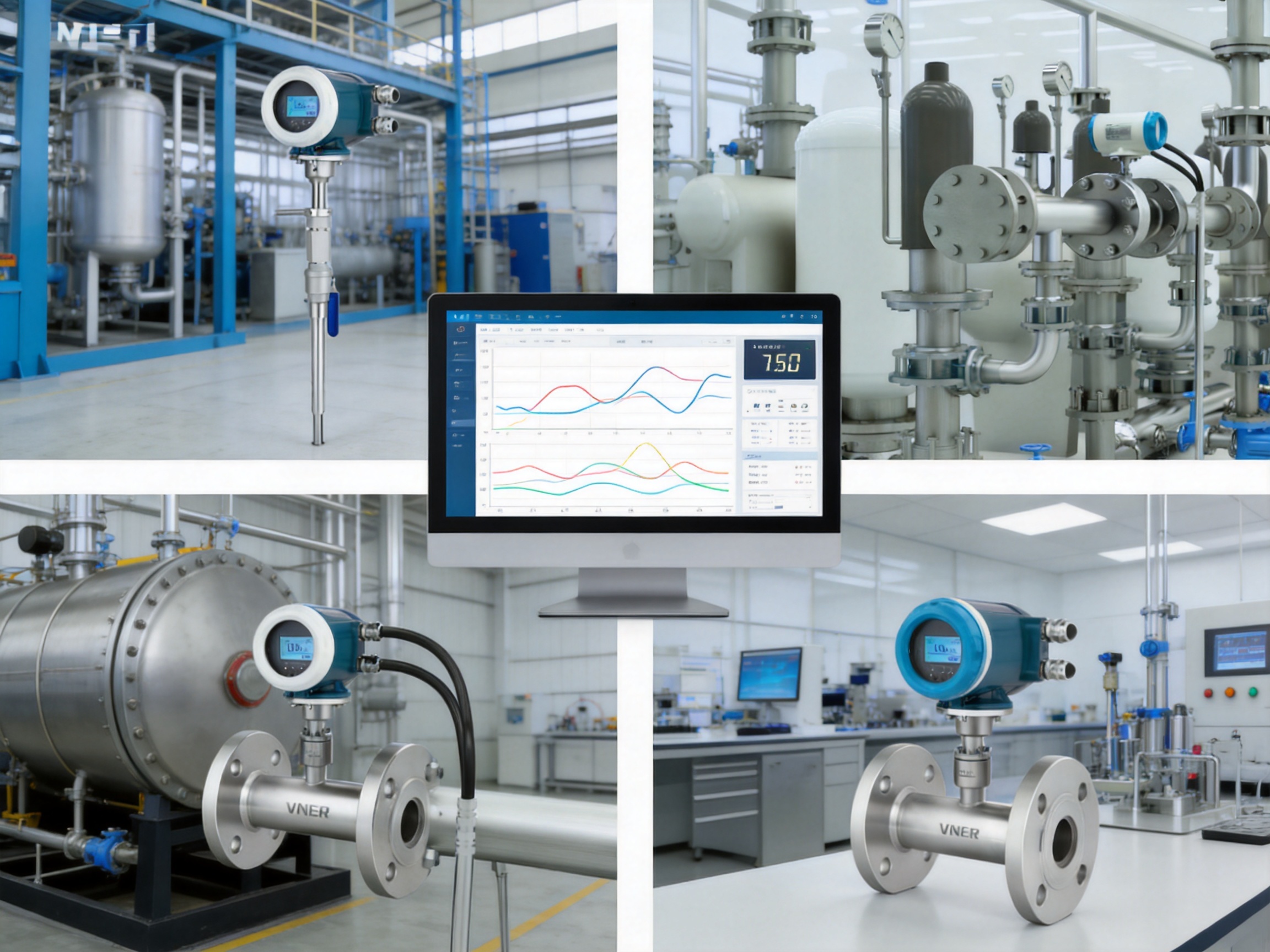
Accurate gas flow measurement is essential for process control, energy management, emissions monitoring, production quality, and plant safety. Industrial facilities increasingly need instruments that can measure changing gas loads, respond quickly to process fluctuations, operate with minimal pressure loss, and communicate reliably with automation systems. Conventional volumetric flowmeters can provide useful process data, but their readings may change substantially when pressure or temperature varies. In many applications, this creates a need for additional pressure and temperature transmitters, external compensation software, and more complicated maintenance procedures.
The ST51 Series Thermal Mass Flowmeter is designed to address these challenges through direct thermal mass flow measurement. Based on the constant temperature difference thermal dispersion principle, the instrument measures the mass flow of clean gases while also monitoring gas temperature. Under specified operating conditions, it does not require separate pressure or temperature compensation transmitters to calculate gas mass flow. This simplifies system design and can reduce installation cost, wiring requirements, commissioning time, and long-term maintenance demands.
Designed for industrial gas applications, the ST51 Series combines a fully welded stainless-steel construction, no moving parts, fast response, wide measurement capability, digital communication, and multiple installation options. It can be supplied as an in-line meter for smaller pipelines or as an insertion meter for larger round and rectangular ducts. A ball-valve insertion configuration can also support hot-tap installation where the process design permits safe insertion and removal without shutting down the entire gas line.
The instrument is manufactured and supported by Jiangsu Vner Electronic Technology Co., Ltd., an industrial flow measurement specialist based in Yangzhou, China. Since 2011, the company has developed electromagnetic, Coriolis, vortex, swirl, turbine, thermal mass, ultrasonic, and variable-area flow measurement technologies for liquid, gas, and slurry applications. Its engineering and manufacturing capabilities support customized solutions for end users, engineering contractors, distributors, and original equipment manufacturers.
Why Direct Gas Mass Measurement Matters
Gas occupies a volume that changes with pressure and temperature. A volumetric reading taken at one set of operating conditions may not represent the same quantity of gas at another set of conditions. For example, a gas pipeline operating during a cold night shift may have a different density from the same pipeline operating during a hot afternoon. Pressure variations caused by compressors, regulators, valves, or changing demand can also alter density.
Traditional volumetric instruments may therefore require external pressure and temperature measurements. A flow computer then uses these inputs to calculate corrected or standard volume flow. This arrangement can work effectively, but it adds instruments, impulse lines or thermowells, electrical connections, software configuration, and possible sources of measurement uncertainty.
Thermal mass flow measurement approaches the problem differently. Instead of measuring only the volume passing through the pipe, the meter determines the heat transfer behavior of the flowing gas. Because heat transfer is related to gas mass flow, the instrument can provide a direct mass flow signal. In many clean-gas applications, this avoids the need for separate pressure and temperature compensation equipment.
Direct mass measurement is valuable when the process objective is based on gas quantity rather than occupied volume. Boiler fuel consumption, compressed-air energy management, nitrogen usage, instrument-air distribution, combustion control, and gas allocation are examples where mass-based information can improve operating decisions.
The ST51 Series can also calculate standard volume flow internally. This gives operators access to a familiar reporting format while preserving the advantages of a direct thermal mass measurement principle. The selected reference conditions and application parameters should be configured correctly during engineering and commissioning so that the displayed standard volume values match the plant’s measurement basis.
Operating Principle of the ST51 Series
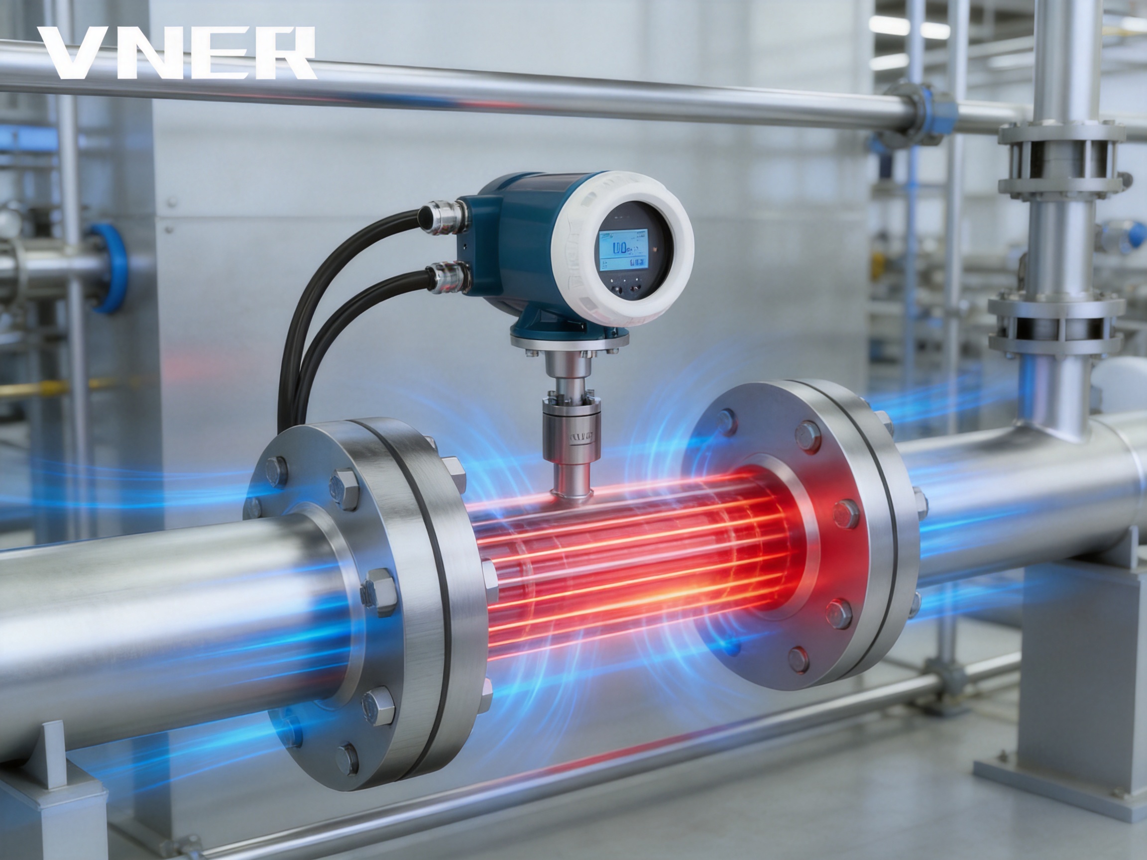
The ST51 Series uses a constant temperature difference, or constant ΔT, thermal dispersion principle based on thermal diffusion. The sensing assembly contains heated and temperature-sensing elements. The transmitter maintains a defined temperature difference between the heated element and the reference temperature of the gas. As gas moves across the sensing area, it carries heat away from the heated element.
At low flow, less heat is removed. At high flow, more heat is removed. The electrical energy required to maintain the selected temperature difference is therefore related to the mass flow of the gas. The transmitter processes this thermal response and converts it into a flow signal. Gas temperature is measured at the same time and can be shown on the local display or transmitted through the available outputs and communication interfaces.
This technique has several practical benefits. It has no impeller, rotor, gear train, bearing, or other moving mechanism exposed to the gas stream. The absence of moving parts reduces mechanical wear and eliminates many common failure modes associated with rotating flow sensors. The sensing element can be manufactured from corrosion-resistant materials selected for the gas service, including 316L stainless steel, Hastelloy, PTFE, and ceramic combinations where applicable.
Thermal dispersion measurement is particularly suitable for clean and dry gases. The gas should generally be single-phase, and non-condensing conditions are preferred. Liquid droplets, heavy contamination, oil carryover, dust deposits, or condensation on the sensor can affect heat transfer and should be evaluated during application selection. Proper filtration, drainage, pipeline orientation, and operating-temperature control may be required for challenging services.
Main Technical Advantages
Direct Mass Flow Measurement
The most important advantage of the ST51 Series is its direct measurement of gas mass flow. The instrument is designed to measure the quantity of gas moving through the pipeline without relying on a separate pressure transmitter and temperature transmitter for basic mass-flow determination. This makes the meter attractive for facilities seeking a compact and integrated gas measurement solution.
Direct mass flow is especially useful when gas conditions vary. In a compressed-air network, demand may change rapidly throughout the day. In a boiler, fuel demand may increase or decrease with production load. In a nitrogen blanketing system, flow may be intermittent and strongly influenced by tank pressure. A direct mass flowmeter gives the control system a measurement that is closely aligned with actual gas consumption.
Negligible Pressure Loss
The ST51 Series is designed to introduce negligible pressure loss into the gas line. This is a significant advantage compared with flow devices that use an obstruction, restriction, nozzle, or pressure-generating primary element. Every unnecessary pressure drop may increase compressor workload, reduce available downstream pressure, or raise operating costs.
Low pressure loss is important in compressed-air plants, low-pressure gas distribution, ventilation systems, and energy-sensitive applications. It also allows the meter to monitor a process without significantly changing the process conditions it is intended to measure. Engineers should still consider the installation configuration, pipe geometry, straight-run requirements, and any fittings near the sensor, but the measurement principle itself does not depend on a large permanent restriction.
Fast Response to Process Changes
The typical response time of the ST51 Series is less than 0.5 seconds. This fast response allows the meter to follow rapid changes in gas demand, valve position, compressor loading, combustion conditions, and intermittent production cycles. A responsive measurement signal can improve control-loop performance and help operators identify sudden changes in consumption.
Fast response is also useful for leak detection. A sudden increase in night-time or idle-period flow may indicate a leaking pipe, open valve, malfunctioning pneumatic device, or unauthorized gas usage. When connected to a supervisory control system, the meter can provide the time-resolved data needed to distinguish normal demand changes from abnormal consumption.
Wide Measuring Range
The ST51 Series provides a wide measuring range, with the available turndown depending on the selected model, sensor design, gas properties, pipe size, and application conditions. This makes the meter suitable for systems that experience both low-load and peak-demand operation.
Variable-load measurement is common in compressed-air networks, process gas headers, laboratory utilities, batch production, burner systems, and intermittent purge lines. A meter that maintains useful sensitivity at low flow while also handling higher flow can reduce the need to install separate instruments for different operating periods.
Application engineers should select the meter using the minimum, normal, and maximum expected flow rates rather than only the nominal pipeline capacity. Gas composition, pressure, temperature, pipe size, and installation orientation should also be included in the sizing review. Correct selection is essential to obtain the expected accuracy and range performance.
No Moving Parts
The ST51 Series uses a thermal sensor rather than a mechanical rotor or impeller. The no-moving-parts design supports long service life and reduces routine mechanical maintenance. It is well suited to applications where the meter may operate continuously or where access for maintenance is difficult.
The absence of moving parts also prevents issues such as bearing wear, rotor imbalance, mechanical friction, and blockage of rotating components. Nevertheless, the sensor must remain clean and compatible with the measured gas. A no-moving-parts design does not eliminate the need for good process filtration or suitable gas conditioning when the service contains contamination or condensation.
Integrated Gas Temperature Measurement
In addition to mass flow, the instrument measures gas temperature. This provides operators with useful process information and can help identify abnormal operating conditions. A rising gas temperature may indicate a compressor problem, heater malfunction, process upset, insufficient cooling, or a change in upstream operating conditions.
Gas temperature can be displayed locally and integrated into a plant monitoring system. The temperature value is also useful during commissioning because it helps verify that the actual process conditions are consistent with the original instrument selection.
Construction and Materials
The meter uses a fully welded stainless-steel construction designed for long-term industrial service. Body materials include stainless steel 304 or 316L, depending on the model and application requirements. Stainless-steel construction provides mechanical strength, corrosion resistance, and compatibility with many common industrial gases.
For more demanding gas services, the sensor can be configured with material combinations such as 316L, Hastelloy, PTFE, and ceramic components. The appropriate material depends on gas composition, moisture content, pressure, temperature, contamination, and chemical compatibility. A detailed medium review should be completed before ordering when the gas contains corrosive, reactive, toxic, or unusual components.
The enclosure is rated IP67, providing protection against dust ingress and temporary water exposure under defined test conditions. This makes the ST51 Series suitable for outdoor installations, utility areas, plant rooms, and industrial locations where equipment may be exposed to rain, humidity, or washdown conditions. The installation should still include appropriate cable glands, grounding, mounting support, and protection from direct mechanical impact.
Explosion-proof Ex d versions are available for selected models. When the meter is installed in a hazardous area, the complete installation must comply with the applicable national and regional requirements. Area classification, certification, cable entries, grounding, barriers, maintenance procedures, and wiring methods must all be reviewed by qualified personnel.
In-Line and Insertion Configurations
In-Line Installation
In-line versions are available for nominal sizes from DN10 to DN100. The meter is installed directly in the gas pipeline, providing a compact and integrated flow measurement point. In-line construction is often preferred for smaller pipelines, skid systems, packaged equipment, laboratory utilities, and dedicated process branches.
In-line meters can provide consistent sensor positioning and a defined flow passage. They are convenient for new pipeline construction or planned shutdowns when a spool section can be installed. Flanged or threaded process connections can be selected according to the pipeline design and pressure rating.
Insertion Installation
Insertion versions are intended for larger round or rectangular ducts where installing a full-bore meter may be impractical or expensive. The sensor probe is inserted through a connection on the pipeline or duct. This configuration can reduce equipment cost and installation weight while allowing measurement on large headers.
An insertion meter should be positioned carefully to obtain a representative gas velocity. The selected insertion depth, sensor orientation, pipe geometry, and upstream and downstream disturbances all affect measurement quality. For large ducts, engineers may need to evaluate the velocity profile and determine whether a single-point measurement is sufficient or whether multiple measurement points are required.
Hot-Tap Capability
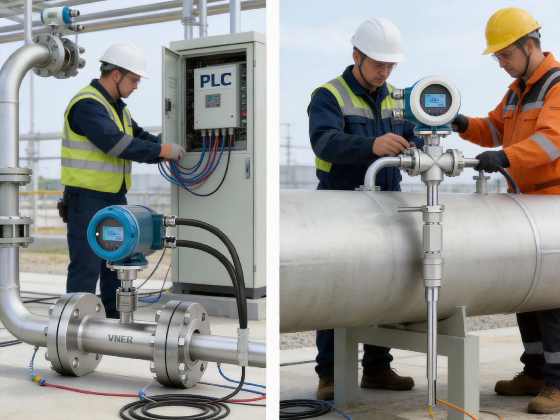
Insertion designs with a ball valve can support hot-tap installation where the project conditions and safety procedures allow it. This arrangement may permit the probe to be inserted or withdrawn while the gas line remains pressurized. Hot-tap work must only be carried out using approved procedures, suitable equipment, and qualified personnel.
The hot-tap option is valuable in operating plants because it can reduce process interruption. It is particularly useful when measuring compressed-air headers, utility gas networks, process exhausts, and distribution lines that cannot easily be shut down. Before installation, the engineering team should verify pressure, temperature, line material, valve rating, access space, isolation requirements, and hazardous-area controls.
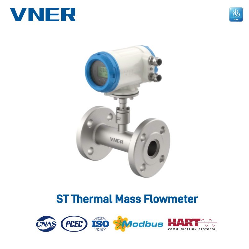
ST51 Series Thermal Mass Flowmeter
Accuracy, Range, and Application Conditions
The stated accuracy of the ST51 Series is ±1.0% of reading plus ±0.5% of full scale under specified conditions. This specification combines a reading-based component and a full-scale component. As with any flowmeter, the actual performance depends on correct sizing, calibration, gas properties, installation quality, stable power, and compliance with the specified operating range.
Users should distinguish between instrument accuracy and total system uncertainty. The overall measurement uncertainty may include calibration uncertainty, gas composition variation, installation effects, pipe diameter tolerance, flow-profile distortion, signal conversion, and data acquisition resolution. A well-designed installation and a clearly defined measurement basis are therefore as important as the instrument’s laboratory specification.
Thermal mass flowmeters are sensitive to gas thermal properties. Different gases remove heat at different rates, so the meter must be configured for the actual gas or gas mixture. Nitrogen, air, hydrogen, natural gas, carbon dioxide, oxygen, and other gases may have different thermal conductivity, specific heat, density, and viscosity characteristics. If the gas composition changes significantly, the application should be reviewed to determine whether recalibration or updated gas parameters are required.
Clean, dry, single-phase gas is generally preferred. Condensation can coat the sensor and alter heat transfer. Dust, oil mist, polymer deposits, and other contaminants may also create an insulating layer or change the effective sensor response. Where contamination is possible, upstream filtration, coalescing, separation, heating, insulation, or periodic inspection should be considered.
The gas-temperature range is model-dependent and can extend from approximately -40°C to +300°C. The actual allowable range depends on the selected sensor, electronics, process connection, sealing materials, and environmental conditions. High-temperature applications should be reviewed carefully to ensure that the transmitter, cable, display, and enclosure remain within their permitted limits.
Electrical Outputs and Digital Communication
The standard output configuration includes a 4–20 mA signal and a pulse or frequency output. The 4–20 mA signal is widely accepted by programmable logic controllers, distributed control systems, data loggers, energy-management platforms, and industrial indicators. It can be assigned to flow, temperature, or another configured process variable according to the selected instrument functions.
The pulse output can be used for totalized flow, batching, counting, or integration with external equipment. For example, a plant can use pulse data to count the quantity of compressed air consumed by a production area or the amount of nitrogen delivered during a batch cycle.
Modbus RS485 communication supports remote configuration, measurement reading, diagnostics, and integration with plant networks. HART communication can provide digital information through the same general instrumentation environment as the analog signal. These interfaces reduce the need for local access when operators need to review parameters, check status, or retrieve process data.
An integral or remote LCD display can show instantaneous flow, totalized flow, gas velocity, and temperature. Local display access is helpful during commissioning, routine inspection, troubleshooting, and maintenance. A remote display option can be useful when the primary transmitter is installed in an inaccessible location, on a high duct, or inside a restricted process area.
Self-diagnostic functions monitor the sensor, electronics, and operating status. Diagnostic information supports maintenance planning and fault tracing. Instead of waiting for a complete loss of output, operators may be able to identify sensor problems, wiring issues, power abnormalities, or measurement-status changes at an earlier stage.
Pressure, Temperature, and Connection Options
The operating pressure range is approximately 1.0 to 6.3 MPa, depending on the model and configuration. The meter is compatible with ANSI 150 and ANSI 300 flange options where specified. Threaded connections are also available for suitable applications. The pressure rating, connection material, sealing method, and installation hardware must be selected together.
Pipeline pressure can influence gas density, mechanical loading, and the suitability of the process connection. The engineering review should consider normal pressure, maximum operating pressure, pressure transients, relief-valve settings, and any possible vacuum condition. The meter should not be operated outside its approved pressure and temperature limits.
Gas temperature affects both the measurement process and the durability of the installation. High-temperature lines may require thermal isolation, extended insertion lengths, remote electronics, or additional support. Low-temperature systems may require protection against condensation and freezing. The meter’s temperature capability should be matched to actual process conditions rather than only the normal operating temperature.
Installation Best Practices
Pipeline Layout
Thermal flowmeters generally perform best when the gas velocity profile is reasonably developed and stable. Elbows, tees, reducers, expanders, partially open valves, control valves, filters, compressors, and other disturbances can create swirl or asymmetrical velocity profiles. The meter should be located with suitable straight pipe lengths according to the project’s installation instructions and application requirements.
When adequate straight length is unavailable, a flow conditioner or an alternative mounting position may be considered. The exact requirement depends on the pipe configuration and meter design. Engineers should avoid placing the sensor immediately downstream of a valve or elbow whenever possible.
Orientation
The ST51 Series can be installed in horizontal or vertical pipelines when the installation is properly designed. The flow direction must match the arrow or configured direction on the instrument. In gas systems where condensation is possible, orientation should prevent liquid from collecting on the sensor. Drainage and low-point management are important in humid gas services.
Sensor Positioning
For insertion meters, the probe must be inserted to the correct depth and aligned with the gas flow. The sensor should not contact the pipe wall, protective lining, internal support, or accumulated deposits. On rectangular ducts, the position should represent the average gas flow as closely as possible. Very large ducts or ducts with uneven flow distribution may require a detailed traverse study.
Grounding and Wiring
Correct grounding and shielding help protect the signal from electromagnetic interference. Signal cables should be routed separately from high-voltage power cables, variable-frequency-drive wiring, and large motor circuits where practical. Cable glands must maintain the enclosure protection rating. Hazardous-area versions require wiring and cable-entry methods that match the relevant certification.
Commissioning
During commissioning, the operator should verify the gas type, engineering units, reference conditions for standard volume calculations, pipe size, flow direction, output range, pulse scaling, communication parameters, and alarm settings. The process should be started gradually when possible so that the signal can be observed at low, normal, and high operating conditions.
A commissioning record should include the instrument serial information, configuration parameters, line conditions, measured values, output verification, and communication test results. This record simplifies future maintenance and provides a baseline for performance comparison.
Applications in Natural Gas and City Gas Systems
Natural gas and city gas distribution systems require dependable flow measurement for energy control, allocation, equipment protection, and operational reporting. The ST51 Series can be used on boiler and burner feed lines, sectional distribution branches, plant utility networks, and selected fuel-gas applications where gas composition and cleanliness are suitable.
In boiler systems, direct gas mass flow helps operators compare fuel input with steam production, combustion-air flow, and process output. The data can be used to analyze boiler efficiency, identify abnormal fuel consumption, and support maintenance decisions. A fast signal can also improve burner control during load changes.
For city-gas distribution inside industrial facilities, meters can be placed at production areas or major consumption points. Totalized data supports energy allocation between departments, shifts, production lines, or tenant areas. Because the meter has negligible pressure loss, it can monitor the network without creating a significant additional burden on the supply system.
Applications in Compressed-Air Networks
Compressed air is often one of the most expensive utilities in a manufacturing facility. Energy is consumed by compressors, dryers, cooling systems, and distribution equipment, yet a considerable portion of the generated air may be lost through leaks or inefficient equipment. Flow measurement at the compressor outlet, main headers, and production branches helps identify where the air is being used.
Insertion ST51 meters can be installed on main and branch headers. Their wide measuring range supports monitoring during low night-time demand as well as peak production. If the meter records significant flow when equipment is supposed to be idle, maintenance teams can investigate leaks, open drains, faulty valves, or pneumatic devices that are operating continuously.
Flow data can also support compressor loading management. When combined with pressure and compressor-status information, the data helps operators understand whether compressors are correctly sized, whether storage capacity is adequate, and whether multiple compressors are operating efficiently. The low pressure loss of the thermal meter is beneficial because it avoids adding a significant permanent restriction to an energy-intensive utility system.
Applications in Nitrogen and Inert Gas Systems
Nitrogen is used for tank blanketing, reactor inerting, pipeline purging, packaging, and oxygen-sensitive manufacturing processes. In these applications, accurate flow measurement supports both safety and cost control. Too little nitrogen may fail to maintain the required inert atmosphere, while excessive nitrogen consumption increases operating cost and may indicate a leak or control problem.
The ST51 Series can measure nitrogen flow with fast response and provide signals to a DCS or PLC through 4–20 mA, pulse, Modbus RS485, or HART communication. The control system can use the flow signal to regulate purge sequences, monitor blanketing demand, and calculate total gas consumption for each process unit.
In chemical and petrochemical facilities, the meter can be applied to nitrogen, hydrogen, instrument air, and other inert gases when the gas composition, pressure, temperature, and cleanliness are compatible with the selected sensor. Hydrogen service requires special attention to material compatibility, area classification, leak prevention, and installation safety.
Applications in Chemical Processing and Drying
Chemical reactors, dryers, coating systems, and process chambers frequently use controlled gas flows to maintain product quality. Nitrogen, dry air, and other inert gases may be used for purging, drying, conveying, blanketing, or controlling the process atmosphere. Flow instability can lead to inconsistent reaction conditions, incomplete drying, coating defects, oxidation, or batch-to-batch variation.
The ST51 Series supplies a continuous flow signal with a response time typically below 0.5 seconds. This enables the control system to react rapidly to changes in demand or valve position. The local display can provide operators with flow, temperature, velocity, and accumulated total information during setup and production.
For these applications, gas cleanliness is especially important. Any solvent vapor, condensate, powder, sticky process material, or chemical deposit that reaches the sensor should be evaluated. Filter selection, sensor material, purge arrangements, and maintenance access should be included in the process design.
Applications in Power Generation, Steel, and Glass
Power plants and industrial furnaces use gas flow measurement to control combustion, improve efficiency, and maintain stable operating conditions. The ST51 Series can be used for selected boiler fuel-gas, combustion-air, and clean flue-gas applications, subject to gas composition and temperature limits.
Combustion control depends on maintaining a suitable air-to-fuel ratio. A reliable gas-flow signal helps the control system adjust fuel valves, combustion air, and burner operating conditions. Monitoring both flow and temperature provides additional process visibility and can help identify changes in combustion performance.
Steel, metallurgy, and glass facilities may use the meter on combustion gas, oxygen-enriched air, furnace utilities, kiln systems, and process gas balancing lines. Stainless-steel construction and a temperature range that can extend to approximately 300°C on selected models support demanding thermal environments. The exact flue-gas application must be reviewed carefully because dust, moisture, corrosive compounds, and variable gas composition can affect thermal measurement.
Applications in Electronics, Food, and Environmental Monitoring
Electronics and semiconductor manufacturing relies on clean dry air, nitrogen, and other process gases. Measurement points may include fabrication tools, coating equipment, packaging lines, purge systems, and facility gas distribution. The fast response and digital communication features of the ST51 Series support automated process monitoring and consumption analysis.
Food and beverage plants use carbon dioxide, nitrogen, compressed air, and other technical gases for carbonation, packaging, preservation, and pneumatic control. Gas usage can vary with production rate, product type, and packaging format. Totalized flow data helps production managers compare gas consumption with output and identify opportunities to reduce waste.
For environmental reporting and process optimization, the meter can be installed on suitable clean vent or exhaust lines. Continuous flow and totalized values may support internal emissions calculations, process balancing, and operating reports. However, the gas composition, moisture, particulate content, and temperature must remain within the meter’s compatibility limits. Applications involving heavily contaminated, wet, corrosive, or chemically unstable exhaust gas may require a different measurement technology or additional gas conditioning.
Advantages Compared with Conventional Flowmeter Technologies
Compared with Mechanical Gas Meters
Mechanical gas meters often use moving elements that can wear over time. Contamination, lubrication requirements, bearing deterioration, and mechanical friction may affect performance. The ST51 Series avoids these issues through a thermal sensing method with no moving parts.
Mechanical meters may also require a larger pressure drop or have limited sensitivity at low flow. The thermal meter’s negligible pressure loss and wide measurement range can be advantageous for variable-load utility systems, especially where low-flow monitoring is important.
Compared with Differential-Pressure Devices
Orifice plates, venturi tubes, and other differential-pressure devices create a relationship between flow and pressure difference. They are widely used and can be highly reliable when properly engineered, but they may create permanent pressure loss. They also commonly require pressure taps, impulse lines, differential-pressure transmitters, and compensation for changing gas density.
The ST51 Series can simplify the measurement installation by directly measuring gas mass flow and integrating temperature measurement. It does not require a large permanent restriction, making it attractive for compressed-air and low-pressure gas systems where energy loss is a concern.
Compared with Vortex Flowmeters
Vortex flowmeters can provide accurate gas volumetric measurement across a useful range, but their performance is related to velocity and fluid conditions. External pressure and temperature compensation may be needed when mass flow or standard volume is required. Vortex meters also require a bluff body in the flow path, which introduces some pressure loss.
The ST51 Series directly targets gas mass flow measurement and uses a low-obstruction thermal sensor. It may therefore provide a simpler solution when the primary objective is gas consumption measurement rather than a broad multi-phase process measurement.
Compared with Turbine Flowmeters
Turbine meters use a rotating rotor and can provide good accuracy in suitable clean-gas services. However, the rotor and bearings are mechanical components that may be affected by contamination, excessive velocity, or wear. Turbine meters may also be less suitable for very low flow or rapidly changing bidirectional operating conditions.
The ST51 Series has no rotating parts and can provide fast response with a wide range. Its suitability for a particular gas depends on thermal properties and cleanliness, so a thermal meter is not automatically a replacement for every turbine application. The correct technology should be selected according to the gas, required accuracy, pressure loss, range, and operating environment.
Compared with Ultrasonic Flowmeters
Ultrasonic flowmeters can be useful for large pipelines and may offer low pressure loss. Their performance can depend on acoustic conditions, gas composition, pressure, pipe geometry, and the quality of the ultrasonic path. Some systems may require more extensive installation or signal-processing arrangements.
The ST51 insertion configuration can offer a compact alternative for large ducts and headers. For clean gas utilities, it combines a relatively simple installation with direct mass flow measurement. Ultrasonic technology may remain preferable for certain large-pipeline, custody-transfer, or specialized gas applications, so project requirements should determine the final choice.
Manufacturing and Engineering Strengths
Jiangsu Vner Electronic Technology Co., Ltd. operates as a specialized industrial flowmeter manufacturer with modern facilities totaling approximately 23,000 square meters across three plants. The company has a technical team of more than 150 people and has delivered over 2,000 engineering projects in more than 30 countries.
This experience supports a practical understanding of real industrial process conditions. Flowmeter selection is not limited to choosing a nominal diameter from a catalog. Gas composition, pressure, temperature, flow range, installation geometry, signal requirements, hazardous-area classification, and maintenance access must all be considered. An engineering-driven manufacturer can use these parameters to recommend an appropriate sensor, connection, material, and transmitter configuration.
In-house calibration is an important part of manufacturing control. Calibration allows the relationship between sensor response and flow output to be verified under controlled conditions. It also supports repeatability, traceability, and quality documentation. For customers with strict project requirements, calibration records and inspection documents can form part of the equipment delivery package.
Certified quality processes help control incoming materials, machining, welding, assembly, electronics integration, pressure testing, sensor inspection, configuration, and final testing. Process consistency is especially important for thermal mass flowmeters because sensor geometry, heating characteristics, electronic stability, and calibration data all influence final performance.
The company’s increasingly automated manufacturing approach supports product consistency and repeatable assembly. Automation can reduce variation in selected production steps, while experienced technical personnel remain responsible for engineering review, process control, testing, and application support. This combination is valuable for both standard orders and customized OEM projects.
Material selection is managed according to the application. Stainless-steel bodies, 316L sensor assemblies, Hastelloy options, PTFE components, and ceramic materials can be considered for different gas environments. The final material combination should be based on chemical compatibility, pressure, temperature, mechanical loading, and expected contamination.
The manufacturer supports EPC contractors, end users, and OEM partners in oil and gas, petrochemical, polysilicon, power, water and wastewater, and general industrial sectors. This broad industry exposure helps the company understand the need for consistent documentation, delivery coordination, instrument tagging, communication compatibility, spare-parts planning, and after-sales technical support.
Selection Guide for Project Engineers
Before specifying an ST51 Series meter, the project engineer should collect the minimum, normal, and maximum gas flow rates. If the system is intermittent, the expected duration and frequency of low-flow and high-flow periods should also be recorded. A meter selected only from the nominal pipe size may not provide the desired performance across the actual process range.
The gas identity and composition should be provided. For a single gas such as nitrogen or compressed air, the application may be straightforward. For natural gas, mixed fuel gas, hydrogen blends, or process gas with changing composition, the composition range should be reviewed. The effect of composition changes on thermal properties and measurement accuracy should be considered.
Pressure and temperature data should include normal values, operating extremes, startup conditions, shutdown conditions, and possible transients. The selected meter must be suitable for the maximum pressure and temperature, not only the average operating point.
Pipe diameter, pipe material, connection type, wall thickness, lining, and available straight-run length should be documented. For insertion installations, the pipe or duct shape, internal dimensions, access location, insertion depth, and valve arrangement are also needed. If the line is rectangular, the flow distribution should be evaluated before deciding whether a single insertion point is representative.
The required outputs should be defined at the beginning of the project. A basic control system may need only 4–20 mA, while a modern plant may require Modbus RS485 or HART for configuration and diagnostics. Pulse output may be necessary for totalization or batching. The local display can be integral or remote according to accessibility requirements.
For hazardous areas, the required protection method and certification must be specified. The area classification, gas group, temperature class, enclosure requirements, cable-entry method, and maintenance procedures should be checked before purchasing. Ex d availability is model-dependent and should be confirmed for the selected configuration.
Maintenance and Long-Term Reliability
The no-moving-parts design reduces mechanical maintenance, but scheduled inspection remains important. The sensor should be checked for deposits, corrosion, mechanical damage, and signs of condensation when the gas service presents such risks. Inspection frequency should be based on actual process conditions rather than a universal interval.
Plant operators should monitor diagnostic information, output stability, totalized flow behavior, and the relationship between gas consumption and production activity. A gradual deviation may indicate sensor contamination, a change in gas composition, a pipeline leak, an installation problem, or a process condition outside the original design basis.
Electrical inspections should include power-supply stability, grounding, cable integrity, terminal tightness, communication quality, and enclosure sealing. Outdoor installations should be checked for water ingress, corrosion, damaged glands, and mechanical stress on the probe or cable.
Calibration intervals depend on the criticality of the measurement, the gas cleanliness, regulatory requirements, process stability, and the customer’s quality system. Critical energy-accounting or control applications may require more frequent verification than non-critical monitoring points. Calibration planning should be coordinated with production shutdowns and maintenance schedules.
Because the company provides multiple flowmeter technologies, customers can also obtain application guidance across different process services. A thermal mass meter is well suited to clean gas measurement, while electromagnetic, Coriolis, vortex, turbine, ultrasonic, swirl, or rotameter technologies may be more appropriate for other fluids or process conditions. Selecting the right technology for each service improves the overall reliability of the plant’s measurement system.
Using Data for Energy Management
Flow measurement becomes more valuable when it is connected to an organized data-management strategy. The ST51 Series can provide instantaneous flow, totalized flow, gas velocity, and temperature. These values can be collected by a PLC, DCS, SCADA system, energy-management platform, or historian.
For compressed air, consumption data can be compared with compressor electricity use. This allows engineers to estimate specific energy consumption and identify periods when the plant produces air without corresponding production output. Branch-level meters can reveal which departments or machines consume the most air.
For natural gas, totalized mass or standard volume flow can be compared with boiler steam production, furnace output, or product throughput. This supports fuel-efficiency analysis and helps identify burner imbalance, insulation problems, control-loop issues, or abnormal operating conditions.
For nitrogen and other technical gases, flow totals can be assigned to individual process units. Consumption benchmarks can be established for each batch or production cycle. Sudden changes in the benchmark may indicate leaks, incorrect valve settings, excessive purging, or a change in production practice.
Q&A
What does the ST51 Series measure?
The ST51 Series measures gas mass flow and gas temperature. It can also calculate standard volume flow internally when the relevant reference conditions are configured.
Does the meter require a separate pressure transmitter?
For basic direct gas mass-flow measurement, the thermal dispersion principle does not require separate external pressure and temperature transmitters. Pressure and temperature data may still be required for specific process calculations, regulatory systems, or applications involving changing gas composition.
What gases can be measured?
The meter is intended for clean gases, including applications involving natural gas, city gas, nitrogen, hydrogen, instrument air, compressed air, carbon dioxide, combustion air, and other compatible technical gases. The actual gas composition, pressure, temperature, contamination level, and thermal properties must be reviewed before selection.
Can the ST51 measure wet or dirty gas?
Clean, single-phase, non-condensing gas is preferred. Condensation, liquid droplets, oil mist, dust, and deposits can affect heat transfer at the sensor. If the gas is wet or contaminated, gas conditioning and a detailed application evaluation are recommended.
What is the accuracy?
The specified accuracy is ±1.0% of reading plus ±0.5% of full scale under specified conditions. Actual system performance also depends on sizing, gas composition, installation, calibration, and process stability.
What is the response time?
The typical response time is less than 0.5 seconds. This allows the meter to respond quickly to changing gas demand and supports applications such as combustion control, batch processing, and leak detection.
Does the meter create a significant pressure drop?
The ST51 Series is designed for negligible pressure loss. This makes it suitable for compressed-air networks, low-pressure gas systems, and applications where energy efficiency is important.
What pipeline sizes are available?
In-line versions are available for DN10 to DN100. Insertion models can be used on larger round or rectangular ducts, subject to application review and suitable sensor positioning.
Can the meter be installed without shutting down the pipeline?
Selected insertion configurations include a ball valve arrangement for hot-tap installation. Whether hot tapping is suitable depends on pressure, temperature, line design, hazardous-area conditions, and approved safety procedures.
What process connections are offered?
Flanged and threaded connections are available, and insertion versions can be supplied with a ball valve for suitable installations. ANSI 150 and ANSI 300 flange compatibility is available for applicable models.
What outputs are available?
The standard outputs include 4–20 mA and pulse or frequency output. Modbus RS485 and HART communication are available for remote configuration, monitoring, and diagnostics.
Can the meter display totalized flow?
Yes. The integral or remote LCD can display instantaneous flow, totalized flow, gas velocity, and gas temperature, subject to the selected display configuration.
Is an explosion-proof version available?
Ex d explosion-proof versions are available for selected models. The required hazardous-area certification and complete installation arrangement must be confirmed during project design.
What materials are used?
The body can be manufactured from stainless steel 304 or 316L. Sensor material options include 316L, Hastelloy, PTFE, and ceramic combinations, depending on the gas and compatibility requirements.
What is the maximum gas temperature?
The gas-temperature range is model-dependent and can extend from approximately -40°C to +300°C. The selected sensor, electronics, process connection, and installation arrangement determine the actual allowable temperature.
How does the ST51 compare with an orifice plate?
The ST51 directly measures gas mass flow and is designed to create negligible pressure loss. An orifice plate measures flow through a differential-pressure relationship and normally creates a permanent pressure drop. An orifice installation may also require pressure taps, impulse lines, a differential-pressure transmitter, and compensation equipment.
How does the ST51 compare with a turbine meter?
The ST51 has no moving parts and is not dependent on a mechanical rotor. This can reduce mechanical wear and maintenance. A turbine meter may be preferable in some clean, stable, high-velocity applications, so the final decision should consider flow range, pressure loss, gas cleanliness, accuracy, and lifecycle requirements.
What information is needed for sizing?
Important information includes gas type and composition, minimum and maximum flow, normal flow, pressure, temperature, pipe diameter, pipe material, connection type, installation orientation, available straight length, output requirements, and hazardous-area classification.
Can the meter be used for energy management?
Yes. Instantaneous and totalized flow data can be used to monitor natural gas, compressed air, nitrogen, and other technical-gas consumption. When connected to a plant information system, the data can support leak detection, cost allocation, production benchmarking, and efficiency analysis.
How often should the meter be calibrated?
Calibration frequency depends on the application, measurement criticality, gas cleanliness, regulatory requirements, and the customer’s quality system. A planned verification schedule should be established during commissioning and adjusted according to operating experience.
Conclusion
The ST51 Series Thermal Mass Flowmeter provides an integrated solution for direct mass measurement of clean industrial gases. Its constant temperature difference thermal dispersion principle measures gas mass flow and temperature without requiring separate external pressure and temperature compensation for basic operation. The result is a compact, low-maintenance instrument suitable for process control, energy management, utility monitoring, and environmental applications.
Negligible pressure loss, fast response, wide measuring capability, no moving parts, stainless-steel construction, IP67 protection, digital communication, self-diagnostics, and in-line or insertion installation options make the series adaptable to many industrial systems. It can measure natural gas, nitrogen, compressed air, instrument air, carbon dioxide, combustion air, and other compatible gases across applications ranging from boilers and reactors to semiconductor facilities and plant-wide utility networks.
The best performance depends on proper engineering. Gas composition, cleanliness, pressure, temperature, pipe geometry, flow range, sensor material, installation position, and communication requirements should all be reviewed before selection. With in-house calibration, controlled manufacturing, application engineering, and experience across multiple flow measurement technologies, Jiangsu Vner Electronic Technology Co., Ltd. is positioned to support both standard and customized industrial instrumentation projects.
For facilities seeking a practical way to improve gas visibility, reduce pressure loss, simplify instrumentation, and strengthen energy-management decisions, the ST51 Series offers a strong combination of measurement performance, industrial durability, and system integration capability.
References
1. International Organization for Standardization. General principles of fluid flow measurement and industrial instrumentation practice.
2. International Organization for Standardization. Guidance on measurement uncertainty and calibration traceability for industrial measuring equipment.
3. American Society of Mechanical Engineers. Industrial flow measurement terminology, installation considerations, and process instrumentation practices.
4. International Electrotechnical Commission. Requirements for electrical equipment enclosures and ingress protection classifications.
5. International Electrotechnical Commission. General principles for electrical equipment used in explosive atmospheres.
6. Manufacturer technical documentation for the ST51 Series Thermal Mass Flowmeter, including operating conditions, configuration options, installation requirements, and maintenance recommendations.
7. Industrial energy-management practices for compressed-air systems, boiler fuel monitoring, technical-gas distribution, and process utility optimization.
Product: ST51 Series Thermal Mass Flowmeter


We offer all our products and services at international standards.
Products
Contact Information
-

+86-18652789521
+86-18052582295
+86-0514-83633600 / 83633900 -

+86-0514-83633600 / 83633900
-

shawn@vnerflow.com
info@vnerflow.com -

No. 11 Xingye Road, Chenji Town Industrial Park, Yizheng, Yangzhou, China
