
 0
 EN
 English
 عربى
 Español
 русский
If you need any help, please feel free to contact us
Home / Author / Cai Shurong — After-Sales Project Coordinator / ST51 Series Thermal Mass Flowmeter: Direct Gas Mass Measurement for Industrial Process Control
ST51 Series Thermal Mass Flowmeter: Direct Gas Mass Measurement for Industrial Process Control
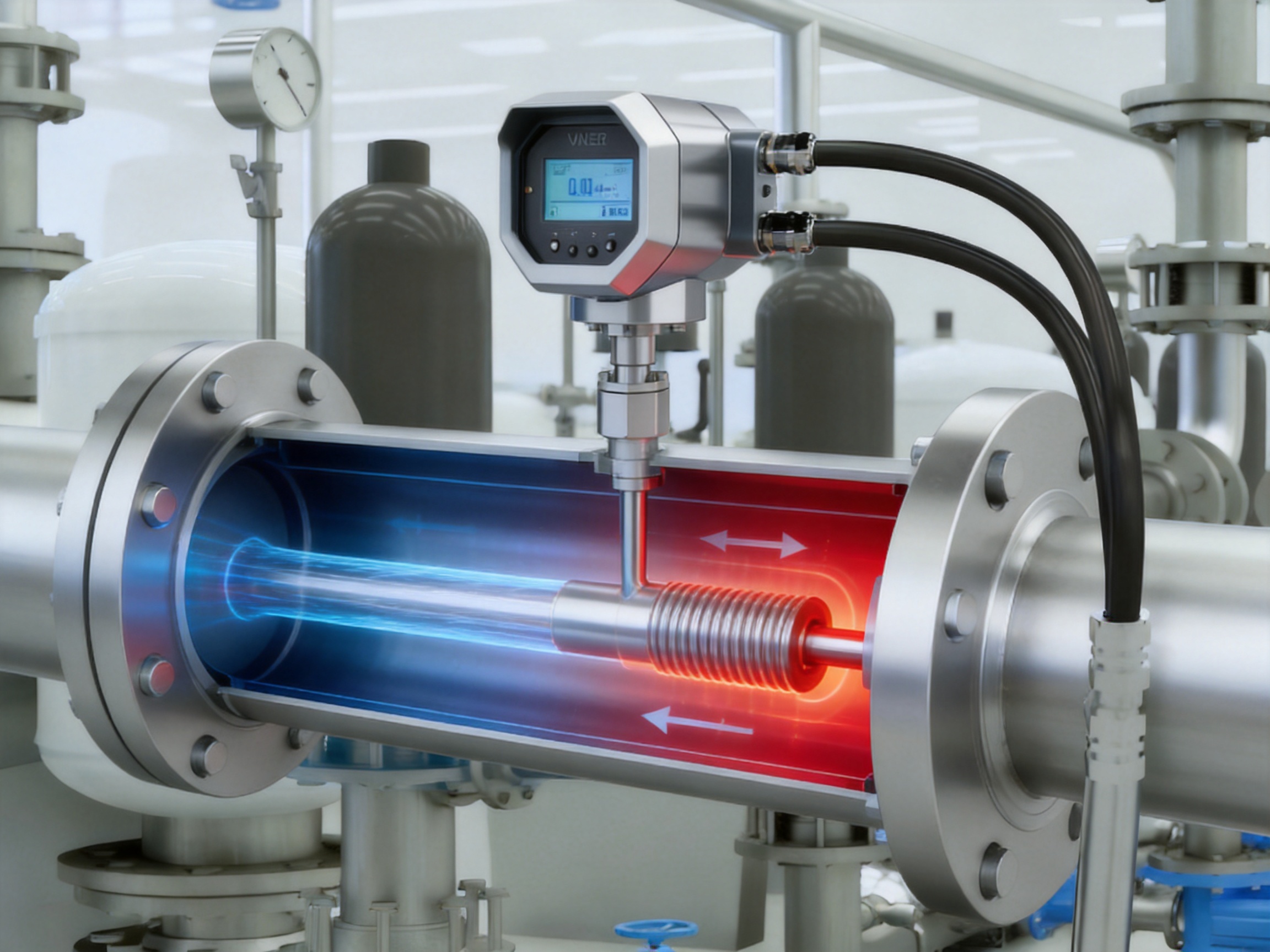
Accurate gas flow measurement is essential for process control, energy management, production consistency, environmental monitoring, and industrial safety. Gas systems are often affected by changing pressure, temperature, density, and operating demand. A flowmeter that measures only volumetric flow may therefore provide misleading information when process conditions vary. The ST51 Series Thermal Mass Flowmeter addresses this challenge by measuring the mass flow of gases directly through a constant-temperature-difference thermal dispersion principle.
Designed for clean, single-phase gases, the ST51 Series combines direct mass measurement, rapid response, negligible pressure loss, broad turndown capability, flexible installation, and intelligent communication functions. It is suitable for in-line pipe installations as well as insertion measurement in larger round or rectangular ducts. Depending on the model and application, the instrument can be supplied with flanged or threaded process connections, hot-tap installation capability, IP67 protection, and explosion-proof construction.
Unlike conventional volumetric flowmeters that may require separate pressure and temperature compensation, the ST51 measures gas mass flow using the heat-transfer characteristics of the flowing medium. This integrated approach can simplify system design, reduce instrumentation requirements, and provide a direct flow signal for gas distribution, combustion control, compressed-air management, inerting, process gas monitoring, and other industrial applications.
1. The Industrial Need for Direct Gas Mass Measurement
Gas flow is commonly expressed in several different forms, including actual volumetric flow, standard volumetric flow, and mass flow. Actual volumetric flow describes the volume occupied by a gas under current operating conditions. Standard volumetric flow converts the gas volume to a defined reference pressure and temperature. Mass flow describes the actual quantity of gas passing through the system, independent of the space occupied by that gas.
Because gases are compressible, their volume changes significantly as pressure and temperature change. A fixed quantity of gas may occupy a very different volume at the inlet of a compressor, inside a high-pressure process line, or downstream of a pressure-reducing valve. For applications involving gas purchasing, fuel consumption, air leakage, material balance, or combustion efficiency, mass-based measurement is often more meaningful than uncorrected volumetric measurement.
Traditional flow measurement systems may use a primary flow element together with pressure and temperature transmitters. The control system then applies compensation calculations to estimate mass flow or standard volume flow. While this method can be effective, it introduces additional components, wiring, calibration requirements, installation points, and potential sources of error. The ST51 Series is designed to measure gas mass flow directly, reducing dependence on external compensation instruments under suitable operating conditions.
Direct mass measurement is especially valuable where gas conditions fluctuate during normal operation. Compressed-air networks, boiler fuel systems, nitrogen blanketing lines, and intermittent process gas applications may experience wide changes in demand. The ST51 can measure these changes quickly and provide a stable output to a PLC, DCS, energy-management platform, or supervisory control system.
2. Operating Principle of the ST51 Series
The ST51 Series uses a constant ΔT thermal mass flow principle based on thermal diffusion. The sensor assembly contains heated and temperature-sensitive elements. During operation, the electronics maintain a defined temperature difference between the heated sensor and the reference temperature of the gas. As gas flows past the sensor, it carries heat away. The amount of heat transferred depends on the mass flow of the gas.
At low flow rates, the heat carried away from the sensor is relatively small. As flow increases, heat transfer increases, and the electronics adjust the heating power or evaluate the thermal relationship required to maintain the preset temperature difference. This thermal response is correlated with gas mass flow. Because the measurement is related to the mass of gas interacting with the sensor, the instrument can provide a direct mass flow output without requiring a separate pressure transmitter for ordinary applications.
The thermal dispersion method offers several practical advantages. It has no rotating impeller, turbine rotor, mechanical displacement element, or obstruction that creates significant permanent pressure loss. The sensing principle also responds rapidly to changing flow conditions. This makes it appropriate for systems where the flow may move from a low night-time load to a high production load within a short period.
The meter can also measure gas temperature. Standard volume flow may be calculated internally when the relevant reference conditions and gas parameters are configured. Users can therefore obtain instantaneous mass flow, totalized flow, gas velocity, temperature, and related process information through the local display or digital communication interface.
2.1 Suitability of the Measured Medium
The ST51 Series is intended primarily for clean gases. Suitable media may include natural gas, city gas, nitrogen, hydrogen, instrument air, compressed air, carbon dioxide, combustion air, and other technical gases, provided that their physical properties and composition are compatible with the selected model and calibration.
Single-phase, non-condensing service is preferred. Condensation, oil contamination, dust, particulate accumulation, or coating on the sensor can affect heat transfer and therefore influence measurement performance. For this reason, the installation should be evaluated with attention to gas cleanliness, moisture control, filtration, upstream process conditions, and the possibility of deposits.
Gas composition is another important consideration. Thermal mass meters are affected by the thermal conductivity, specific heat, density, viscosity, and composition of the measured gas. The ST51 should be selected and configured for the expected gas or gas mixture. If the gas composition changes substantially during operation, the measurement behavior may change as well. Engineering review and appropriate calibration are recommended for mixed, variable, wet, or chemically aggressive gases.
3. Main Technical Characteristics
| Item | ST51 Series characteristic |
| Measuring principle | Constant ΔT thermal mass flow based on thermal diffusion |
| Measured medium | Clean gases; single-phase and non-condensing service preferred |
| Measured variables | Gas mass flow, gas temperature, and internally calculated standard volume flow |
| Accuracy | ±1.0% of reading plus ±0.5% of full scale under specified conditions |
| Nominal size | DN10 to DN100 for in-line models; insertion models for larger ducts |
| Process connections | Flanged, threaded, or insertion connection with ball valve for hot-tap installation |
| Operating pressure | 1.0 to 6.3 MPa, with compatibility for ANSI 150 and ANSI 300 flanges |
| Gas temperature | -40 to +300 °C, depending on model |
| Enclosure protection | IP67 |
| Body materials | Stainless steel 304 or 316L |
| Sensor materials | 316L, Hastelloy, PTFE, ceramic combinations, according to compatibility requirements |
| Outputs | 4-20 mA and pulse/frequency output |
| Communication | Modbus RS485 and HART |
| Response time | Typically less than 0.5 seconds |
| Power supply | 24 VDC or 220 VAC |
| Hazardous-area option | Ex d explosion-proof versions available according to model |
The listed specifications describe the general capabilities of the series. Final performance depends on the selected size, gas composition, pressure, temperature, installation conditions, calibration, and process connection. Proper sizing is important because thermal flowmeters perform best when the meter range corresponds appropriately to the expected minimum, normal, and maximum operating flows.
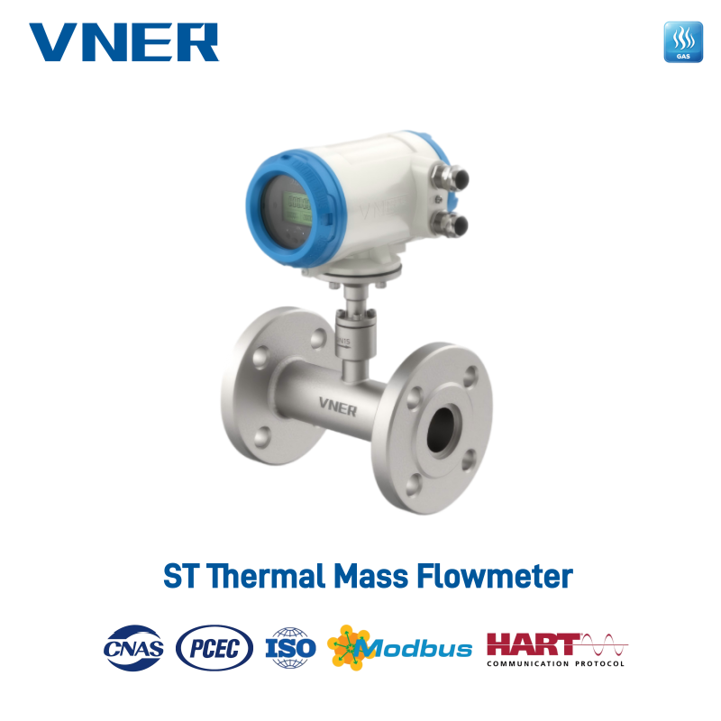
ST51 Series Thermal Mass Flowmeter
4. Advantages Compared with Conventional Gas Flowmeter Technologies
Industrial users may choose from vortex, turbine, differential-pressure, positive-displacement, ultrasonic, Coriolis, and thermal mass flowmeters. Each technology has an appropriate application range. The ST51 Series is particularly competitive in clean-gas services where users need direct mass flow measurement, low pressure loss, high sensitivity, flexible installation, and practical integration with industrial control systems.
4.1 Direct Mass Flow without External Compensation
A differential-pressure meter normally determines flow from the pressure drop across an orifice, nozzle, or other primary element. To calculate mass flow accurately, the system may also need pressure and temperature inputs. A vortex or turbine meter generally measures velocity or volumetric flow, which may then require compensation if operating conditions change.
The ST51 measures mass flow through thermal interaction with the gas. This can reduce the need for separate pressure and temperature transmitters in many standard applications. Fewer instruments may mean a simpler process design, fewer impulse lines, reduced installation labor, and fewer calibration points. The result is not only a more compact measurement system but also a potentially lower total cost of ownership.
Internal standard-volume calculation provides additional flexibility. Users who need standard cubic meters or another configured reference volume can use the meter’s internal calculation, while users who require direct mass measurement can use the mass flow output. Configuration must be based on the correct reference conditions and gas characteristics.
4.2 Negligible Pressure Loss
Pressure loss is an important design concern in compressed-air networks, low-pressure gas systems, burner trains, and energy-sensitive installations. Every unnecessary pressure drop may require additional compressor or blower energy. It can also reduce available pressure at downstream equipment.
The ST51 Series has no moving parts and is designed to introduce negligible pressure loss. Compared with restrictive primary elements, this characteristic can help preserve line pressure and reduce the energy penalty associated with measurement. It is particularly beneficial in compressed-air monitoring, where the measurement objective is often to identify energy consumption and leakage without adding a significant new load to the network.
4.3 Fast Response to Changing Flow
The typical response time is less than 0.5 seconds. This allows the meter to react quickly to demand changes, valve movements, burner adjustments, compressor cycling, or intermittent process operation. Fast response is useful for closed-loop control because the control system receives updated flow information without a long measurement delay.
In combustion applications, rapid feedback can support closer control of the gas-to-air ratio. In inerting systems, it can help regulate nitrogen consumption as tanks or reactors transition between operating states. In compressed-air systems, it can reveal short-duration demand peaks and support more accurate analysis of production-related consumption.
4.4 Wide Measuring Range and Turndown
Many industrial gas systems operate across a wide range. A plant may use very little gas during standby periods and significantly more during production. A meter selected only for the normal flow may become saturated at peak demand, while a meter selected for the maximum flow may provide poor resolution at low flow.
The ST51 Series provides a wide measuring range, with the practical turndown depending on the model, sensor, gas, and application. This makes it suitable for variable-load systems, intermittent gas lines, branch networks, compressor headers, and utility monitoring. Accurate selection remains essential, but the thermal principle can provide useful sensitivity across a broad operating range.
4.5 No Moving Parts
Mechanical flowmeters may contain bearings, rotors, gears, or other moving elements that wear over time. Contamination, vibration, excessive velocity, or poor lubrication can affect their performance. The ST51 sensor contains no moving mechanical flow element. Its welded stainless-steel construction and solid-state electronic design support long-term stability with limited routine maintenance.
The absence of moving parts does not eliminate the need for inspection. Sensors should still be protected from deposits, condensation, corrosive attack, and unsuitable gas conditions. However, the maintenance profile is generally simpler than that of mechanical meters because there is no rotor or bearing assembly to service.
4.6 Flexible Installation in Pipes and Ducts
The series includes in-line configurations for DN10 to DN100 piping and insertion configurations for larger round or rectangular ducts. Insertion models can be supplied with a ball valve for hot-tap installation where the process design permits. This provides a practical method for measuring large headers without installing a full-bore meter spool.
Horizontal and vertical installation are possible when the installation follows the applicable flow-direction, straight-run, sensor-orientation, and service requirements. Insertion technology can reduce material and installation costs on large ducts, especially in compressed-air distribution, combustion-air systems, utility headers, and plant-wide monitoring networks.
5. Construction, Materials, and Environmental Protection
The ST51 Series uses a fully welded stainless-steel body. Stainless steel 304 is suitable for many general industrial services, while 316L can provide improved resistance for more demanding environments. The appropriate body material should be selected according to gas composition, moisture, temperature, pressure, cleaning requirements, and external environmental exposure.
Sensor materials may include 316L, Hastelloy, PTFE, and ceramic combinations. This range allows the sensing assembly to be matched more closely to the measured medium. Hastelloy may be considered for more corrosive conditions, while PTFE or ceramic components may be appropriate where material compatibility or high-temperature performance is important. The final selection should be verified against the chemical composition and operating conditions.
The IP67 enclosure is designed for protection against dust ingress and temporary water immersion under defined test conditions. This makes the transmitter suitable for outdoor installations, utility areas, process plants, and locations exposed to rain, spray, or washdown risk. Cable glands, conduit entries, mounting orientation, and installation practices must still be selected correctly to maintain the intended enclosure protection.
For hazardous areas, Ex d explosion-proof versions are available depending on the model. Hazardous-area installations require compliance with the applicable certification, wiring, grounding, cable-entry, inspection, and maintenance requirements. The instrument must be selected according to the gas group, temperature class, zone or division classification, and local regulations.
6. Intelligent Transmitter and Communication Functions
The ST51 transmitter is designed for integration into modern industrial control architectures. A 4-20 mA output provides a widely accepted analog signal for PLC, DCS, SCADA, and energy-management systems. Pulse or frequency output can be used for totalization, batching, counting, or connection to equipment that receives a frequency-based flow signal.
Modbus RS485 communication supports digital data exchange, remote configuration, process-value reading, and diagnostic access. HART communication allows users to access digital information while retaining the familiar 4-20 mA signal. This combination makes the meter suitable for both new installations and modernization projects that must connect to existing control infrastructure.
The local HMI may be integral or remote, depending on the configuration. Typical display values include instantaneous flow, totalized flow, gas velocity, and gas temperature. The display allows operators to check process conditions at the instrument without relying entirely on the control room.
Self-check functions can monitor the sensor, electronics, and general status of the instrument. Diagnostic information supports maintenance planning and fault tracing. Instead of waiting for a complete loss of signal, maintenance personnel may use status information to identify abnormal conditions, sensor problems, or configuration issues earlier.
7. Manufacturing Strength and Engineering Capabilities
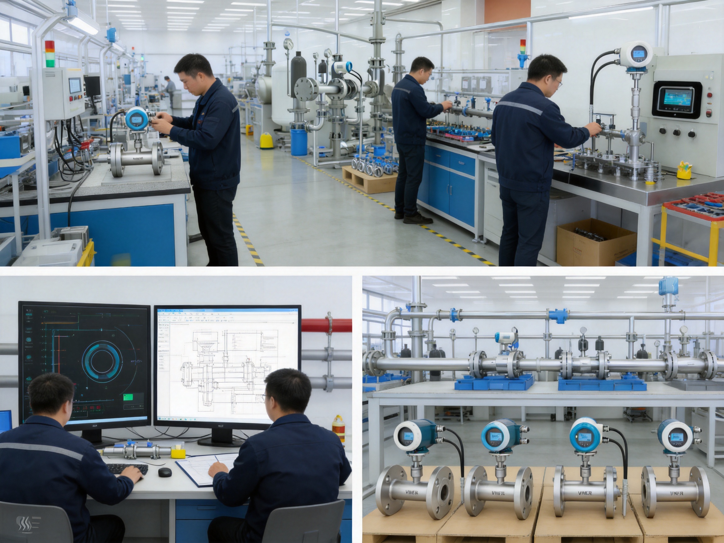
The performance of an industrial flowmeter depends not only on its measurement principle but also on the quality of its mechanical construction, electronics, calibration, software, assembly, and final inspection. Jiangsu VNER Electronic Technology Co., Ltd. is a specialized industrial flowmeter manufacturer based in Yangzhou, China. Established in 2011, the company develops and manufactures electromagnetic, Coriolis, vortex, swirl, turbine, thermal mass, ultrasonic, and rotameter products for liquid, gas, and slurry applications.
The company operates modern facilities covering approximately 23,000 square meters across three plants and has a technical team of more than 150 people. Its product range and project experience allow thermal mass flowmeter development to benefit from broader knowledge of industrial instrumentation, process connections, electronics, calibration, and application engineering.
More than 2,000 engineering projects have been delivered in over 30 countries. This international project experience is valuable because flowmeter installations often differ substantially from one site to another. Pipe size, gas composition, ambient conditions, hazardous-area requirements, control-system interfaces, and customer documentation may all require careful coordination.
7.1 In-House Calibration and Quality Control
Thermal mass flow measurement depends on the relationship between sensor behavior and gas properties. Calibration is therefore a critical part of production. In-house calibration capabilities help the manufacturer verify performance, maintain process consistency, and provide traceability for instruments supplied to different industries.
Calibration and inspection should cover the sensor response, transmitter electronics, output signals, communication functions, temperature measurement, display behavior, pressure integrity, enclosure condition, and configuration data. Consistent procedures reduce variation between instruments and support repeatable performance in the field.
Certified quality processes provide a framework for controlling incoming materials, assembly operations, process inspections, final testing, documentation, and nonconformance handling. For industrial users, this is important because the meter is often part of a larger control or energy-management system. Stable manufacturing quality helps reduce commissioning problems and unexpected replacement requirements.
7.2 Automated and Repeatable Production
Increasingly automated manufacturing can improve assembly consistency and production efficiency. Automation is especially useful for repeatable operations such as electronic assembly, welding-related processes, dimensional verification, serial-number tracking, and test sequencing. Human engineering judgment remains important, but controlled production steps can reduce variation and improve traceability.
For a thermal mass flowmeter, mechanical alignment between the sensor and the flow path is important. The sensor must be positioned correctly, protected from mechanical damage, and sealed properly. Electronics must be assembled with attention to grounding, insulation, signal integrity, and environmental protection. A controlled production process helps ensure that these details are handled consistently.
7.3 Engineering-Driven Sizing and Selection
Flowmeter selection should not be based solely on nominal pipe size. The expected minimum, normal, and maximum flow, gas composition, pressure, temperature, density, viscosity, installation orientation, straight pipe conditions, and required output signals all influence the selection.
VNER supports engineering-driven sizing and selection so that the ST51 can be matched to the actual service rather than treated as a one-size-fits-all instrument. This is particularly important for insertion meters, variable gas mixtures, high-temperature lines, low-flow applications, and systems where the measured gas may contain moisture or contaminants.
Application review can also identify when a thermal mass flowmeter is not the most appropriate choice. For example, heavily contaminated gas, unstable composition, significant condensation, or multiphase service may require a different measurement technology or additional conditioning. Responsible selection improves measurement reliability and helps customers avoid applying the meter outside its intended operating range.
7.4 Support for EPC, OEM, and End-User Projects
The company works with engineering, procurement, and construction contractors, end users, and original equipment manufacturers. These customers may require different forms of support. EPC contractors often need technical submittals, dimensional drawings, compliance documents, inspection records, and consistent delivery across multiple instruments. OEM customers may require repeatable configurations, customized outputs, private labeling, or integration into packaged equipment.
End users typically focus on measurement stability, ease of operation, spare-parts support, communication compatibility, and long-term maintenance. A manufacturer with experience across these customer groups can provide a more complete project response, from initial sizing through commissioning and after-sales service.
8. Application Areas
8.1 Natural Gas and City Gas Distribution
The ST51 can be installed on natural-gas or city-gas lines supplying boilers, burners, furnaces, and plant utility systems. Direct mass flow measurement supports fuel consumption analysis, sectional metering, energy allocation, and boiler efficiency studies.
In a boiler house, in-line models installed on DN25 to DN80 lines can measure fuel gas flow and temperature. The plant control system can use the data for combustion management, production reporting, and comparison of gas consumption against steam output. Where standard volume or mass-based accounting is needed, the meter can provide the configured flow variable without necessarily requiring separate external compensation instruments.
8.2 Nitrogen Inerting and Blanketing
Nitrogen is widely used to reduce oxygen exposure in storage tanks, reactors, pipelines, and packaging systems. Excessive nitrogen flow increases operating cost, while insufficient flow may compromise the intended inerting function. The ST51 provides a fast and sensitive signal for monitoring nitrogen consumption and controlling supply valves.
Modbus RS485 or HART communication allows the measured flow to be transferred to a DCS or plant monitoring system. Operators can review instantaneous flow, total consumption, gas temperature, and diagnostic status. This supports both safety-related operating practices and resource management.
8.3 Compressed-Air Network Monitoring
Compressed air is often one of the most expensive industrial utilities because energy is consumed to compress, dry, distribute, and condition the air. Leaks, oversized equipment, pressure fluctuations, and poor demand management can increase costs without directly increasing production.
Insertion ST meters can be installed on main headers, production areas, and branch lines. Because the instrument has negligible pressure loss, it can monitor the network without adding a significant restriction. Wide measuring capability helps capture low night-load flows as well as peak production demand. Comparing flow at different points can help identify leakage, unusual consumption, and inefficient equipment operation.
Totalized flow data can also be used for energy allocation between departments, production lines, buildings, or individual machines. When combined with compressor electrical data, the measurement can support specific-energy calculations and long-term efficiency projects.
8.4 Combustion Air and Flue-Gas Measurement
Boilers, furnaces, kilns, and glass-melting systems depend on controlled gas and air flows. Too much air can reduce efficiency by carrying excess heat out of the process, while too little air can result in incomplete combustion, unstable operation, or increased emissions.
ST meters installed on suitable combustion-air or clean flue-gas lines can provide real-time flow feedback. The gas temperature capability, which may reach up to 300 °C depending on the model, supports selected thermal-process applications. Stainless-steel construction helps the meter withstand demanding industrial environments, provided that the measured gas is compatible and free from excessive deposits.
Flue-gas service requires careful evaluation. Dust, condensation, corrosive compounds, and changing gas composition can affect any thermal sensor. Where the flue gas is dirty, wet, or chemically aggressive, filtration, conditioning, special materials, or an alternative technology may be required.
8.5 Chemical Reactors, Dryers, and Coating Systems
Reactors, dryers, coating lines, and other process systems often use nitrogen, dry air, hydrogen, or inert gases. Stable flow control can influence reaction conditions, drying rates, coating uniformity, product quality, and workplace safety.
The ST51’s fast response and digital communication functions help the control system respond to fluctuating process demand. Its direct mass flow measurement is useful where the quantity of gas, rather than only its line volume, is important to the process recipe or material balance.
8.6 Food, Beverage, and Packaging Operations
Carbon dioxide and nitrogen are used in carbonation, modified-atmosphere packaging, beverage production, and product preservation. Compressed air is also used throughout pneumatic equipment and packaging lines. Flow measurement can help verify gas consumption, maintain packaging conditions, and identify leaks in pneumatic systems.
Material selection and cleanliness requirements should be reviewed for each application. The meter should be installed where the gas is clean and non-condensing, and the wetted materials should be compatible with the process and cleaning procedures.
8.7 Electronics and Semiconductor Manufacturing
Clean dry air and nitrogen are important utilities in semiconductor, electronics, coating, and packaging facilities. Small deviations in gas supply can affect process stability, while undetected leaks can create significant operating costs across a large facility.
In-line meters can monitor smaller process branches, while insertion models can monitor larger plant headers. Digital outputs allow the flow data to be connected to facility-management and production-monitoring platforms. The final installation must meet the cleanliness, material, and environmental requirements of the facility.
8.8 Environmental and Vent Monitoring
The ST51 can be used on suitable clean vent or exhaust lines to monitor gas discharge and support internal environmental reporting. Totalized gas quantities can provide useful information for process optimization, production analysis, and emissions-related calculations where the gas composition remains within the meter’s compatibility limits.
Environmental applications require careful attention to gas composition, moisture, temperature, particulates, and regulatory measurement requirements. The ST51 is a process gas flowmeter and should not automatically be considered a certified emissions-monitoring instrument unless the complete system meets the applicable regulatory requirements.
9. Installation and Commissioning Considerations
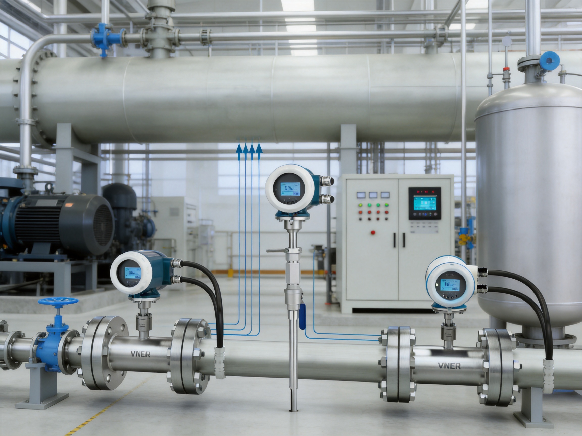
Correct installation is essential for achieving the specified accuracy. Before installation, the user should confirm the pipe size, gas type, operating pressure, operating temperature, expected flow range, flow direction, connection standard, power supply, output requirements, ambient conditions, and hazardous-area classification.
The sensor should be located where the gas is adequately mixed and where flow disturbances are minimized. Valves, elbows, reducers, expanders, tees, compressors, filters, and regulators can create velocity profiles or turbulence that influence the measurement. Appropriate straight-run requirements should be confirmed from the product documentation and application design.
For insertion installations, the sensor must be positioned at the correct insertion depth and orientation. The insertion point should represent the average flow profile across the pipe or duct. Large rectangular ducts may require additional consideration because velocity distribution can vary across the duct cross-section. In some cases, multiple measurement points or a carefully selected insertion location may be necessary.
A ball-valve insertion assembly can support hot-tap installation where the piping design and safety procedures permit. Hot-tap work must be performed by qualified personnel using equipment rated for the pressure, temperature, gas, and hazardous-area conditions. Isolation, purging, leak testing, and work-permit procedures are essential.
The power supply may be 24 VDC or 220 VAC according to the selected configuration. Signal wiring should be separated from strong electromagnetic interference sources where practical. Proper grounding, shielding, cable selection, and enclosure sealing help protect the analog and digital signals from interference and moisture.
After mechanical and electrical installation, commissioning should include verification of flow direction, sensor configuration, gas parameters, range settings, output scaling, totalizer units, communication address, baud rate, parity, HART parameters, alarm settings, and display units. The measured reading should be compared with expected process conditions or an independent reference where available.
10. Maintenance and Long-Term Reliability
The ST51 Series is designed for low maintenance because it has no moving flow parts. Routine maintenance should nevertheless include visual inspection of the transmitter, cable entries, process connection, mounting hardware, and enclosure. Operators should check for corrosion, vibration damage, moisture ingress, abnormal temperature exposure, and signs of gas leakage.
Sensor condition is particularly important in thermal dispersion measurement. A coating of oil, dust, scale, or condensate can modify heat transfer and affect the reading. If the process gas is not consistently clean and dry, the maintenance plan should include inspection and cleaning at an interval appropriate to the service.
Diagnostic information from the transmitter can support condition-based maintenance. Sensor status, electronics status, and communication alarms may help technicians distinguish between a process change, a wiring fault, a sensor problem, and an incorrect configuration. Maintaining accurate records of alarms, calibration checks, cleaning activities, and process conditions can improve long-term reliability.
Periodic verification should be planned according to the application’s accuracy requirements. Critical fuel, custody-related, environmental, or control applications may require more frequent verification than general utility monitoring. The verification method should be suitable for gas flow measurement and should account for the selected gas, operating range, and installation configuration.
11. Selecting the Right ST51 Configuration
The first selection question is whether the gas is clean, single-phase, and compatible with thermal measurement. The second is the required flow range. Users should provide minimum, normal, and maximum flow values rather than only the nominal pipe size. This information helps determine whether an in-line or insertion model is more suitable and whether the desired turndown can be achieved.
Pressure and temperature must also be reviewed. The series supports operating pressures from approximately 1.0 to 6.3 MPa and gas temperatures from approximately -40 to +300 °C, depending on the model. The actual configuration must remain within its specific pressure, temperature, material, and certification limits.
Process connection selection depends on the existing piping standard and maintenance requirements. Flanged meters may be preferred for larger lines or systems requiring robust mechanical connection. Threaded meters can be practical for smaller pipe sizes. Insertion meters are often advantageous for large headers and ducts, especially where cutting out a pipe section would be costly or disruptive.
Material selection should consider corrosion, moisture, cleaning chemicals, and expected service life. Stainless-steel 304 may be suitable for general utility gas, while 316L, Hastelloy, PTFE, or ceramic combinations may be preferred for more demanding media.
Finally, the user should define the required power supply, signal outputs, communication protocol, local display, enclosure protection, and hazardous-area certification. Early specification of these details helps prevent changes during installation and ensures that the meter integrates correctly with the plant control system.
12. Practical Project Example: Industrial Boiler Gas Measurement
Consider an industrial boiler plant with several natural-gas supply branches serving different burners. The plant wants to compare fuel consumption, improve combustion control, and evaluate boiler efficiency. An ST51 in-line meter can be installed on each selected branch, subject to the line size and gas conditions.
The meter supplies a direct mass flow signal through 4-20 mA and can provide a pulse output for totalization. Modbus RS485 or HART communication can transfer flow, temperature, totalized quantity, and diagnostic information to the control system. Because external pressure and temperature transmitters may not be required for the basic mass-flow measurement, the instrumentation arrangement can be simplified.
During low production periods, the meter can record reduced fuel demand. During peak operation, its rapid response can track changes caused by burner control. By comparing fuel flow with steam production, operators can calculate trends in boiler efficiency and identify abnormal consumption. If combustion air is measured as well, the control system can evaluate the air-to-fuel relationship more effectively.
The value of the installation depends on correct gas calibration, suitable straight-run conditions, clean gas, accurate totalizer configuration, and a maintenance plan. The measurement should be reviewed as part of the complete combustion-control system rather than as an isolated instrument.
13. Practical Project Example: Compressed-Air Leak Management
A manufacturing plant may install insertion ST meters on the main compressed-air header, production-area branches, and selected equipment groups. The main-header meter records total plant air consumption, while branch meters show where the air is being used.
During production hours, branch flow can be compared with equipment output. During non-production periods, unexpected flow may indicate leaks, open valves, improperly adjusted regulators, or equipment that has not been isolated. Because the ST51 introduces negligible pressure loss, it can remain installed without significantly affecting the distribution network.
Long-term trends can show whether maintenance activities are reducing consumption. Totalized flow can be allocated to production departments, and high-demand periods can be compared with compressor loading. This transforms the flowmeter from a simple display instrument into a tool for energy management and operational improvement.
14. Why the ST51 Series Is a Strong Industrial Choice
The ST51 Series is competitive because it combines several benefits that are not always available in one gas-flow instrument. It measures mass flow directly, responds quickly, introduces negligible pressure loss, contains no moving parts, supports broad installation options, and provides standard industrial signals and communication protocols.
Its stainless-steel construction, IP67 protection, optional high-temperature capability, and available Ex d versions support use in demanding industrial locations. Its in-line and insertion configurations allow the same product family to address small pipe measurements and large duct or header applications.
The manufacturer’s broader strengths also contribute to product value. In-house calibration, engineering-based selection, controlled quality processes, modern facilities, a substantial technical team, international project experience, and support for EPC, OEM, and end-user requirements provide a foundation for reliable project execution.
For users, the most important advantage is not simply the instrument specification. It is the combination of suitable measurement technology, correct application engineering, consistent manufacturing, practical communication functions, and long-term serviceability. When these elements are aligned, the ST51 can support more efficient, transparent, and controllable gas systems.
15. Questions and Answers
Q1: What does the ST51 Series measure?
The ST51 measures the mass flow of gases directly. It can also measure gas temperature and calculate standard volume flow internally when configured with the appropriate reference conditions.
Q2: Does the ST51 require separate pressure and temperature compensation?
For direct gas mass-flow measurement under suitable operating conditions, the meter does not require separate external pressure and temperature transmitters. The instrument also measures gas temperature internally. System requirements and gas characteristics should still be reviewed for each application.
Q3: What gases are suitable for the ST51?
The meter is designed for clean gases such as natural gas, city gas, nitrogen, hydrogen, instrument air, compressed air, carbon dioxide, combustion air, and other compatible technical gases. The gas should preferably be single-phase and non-condensing.
Q4: Can the ST51 measure wet or dirty gas?
Thermal mass flowmeters perform best with clean, dry gas. Condensation, oil, dust, or deposits on the sensor may influence heat transfer and measurement accuracy. Wet or dirty applications require engineering evaluation, possible gas conditioning, special materials, or another measurement technology.
Q5: Does the meter cause a pressure drop?
The ST51 is designed to create negligible pressure loss because it has no significant internal obstruction or moving flow element. This is beneficial for compressed-air, low-pressure, and energy-sensitive systems.
Q6: What is the typical response time?
The typical response time is less than 0.5 seconds. Actual dynamic behavior depends on the selected model, gas conditions, signal filtering, installation, and control-system settings.
Q7: What pipe sizes are available?
In-line models are available for nominal sizes from DN10 to DN100. Insertion models can be used for larger round or rectangular ducts when the installation is properly designed.
Q8: Can the meter be installed without shutting down the process?
Insertion versions with a ball valve may support hot-tap installation where permitted by the piping design and safety procedures. Hot-tap work must be performed by qualified personnel using equipment appropriate for the pressure, temperature, gas, and hazardous-area conditions.
Q9: What output signals are available?
The standard output arrangement includes 4-20 mA and pulse or frequency output. Modbus RS485 and HART communication are available for digital integration, configuration, and diagnostics.
Q10: Is a local display available?
Depending on the configuration, the meter can have an integral or remote LCD. Typical display information includes instantaneous flow, totalized flow, gas velocity, and temperature.
Q11: Is the ST51 suitable for hazardous areas?
Ex d explosion-proof versions are available for selected models. The exact certification and configuration must match the site’s hazardous-area classification, gas group, temperature class, and local regulations.
Q12: What materials are used for the meter?
The body is available in stainless steel 304 or 316L. Sensor materials may include 316L, Hastelloy, PTFE, and ceramic combinations, depending on the gas and compatibility requirements.
Q13: How does the ST51 compare with a turbine flowmeter?
A turbine meter uses a rotating mechanical element and generally measures volumetric flow. The ST51 has no moving parts and measures gas mass flow thermally. The best choice depends on the gas cleanliness, required accuracy, flow range, pressure, temperature, and application conditions.
Q14: How does the ST51 compare with a differential-pressure meter?
A differential-pressure meter typically requires a primary restriction and may require pressure and temperature compensation for mass-flow calculations. The ST51 has negligible pressure loss and directly measures gas mass flow under suitable conditions. Differential-pressure technology may still be preferred for certain high-temperature, high-pressure, dirty-gas, or standardized applications.
Q15: What information should be provided for quotation and sizing?
Users should provide gas type and composition, minimum and maximum flow, normal flow, pressure, temperature, pipe or duct size, process connection, installation orientation, required outputs, power supply, ambient conditions, hazardous-area classification, and any material or certification requirements.
Conclusion
The ST51 Series Thermal Mass Flowmeter provides a practical solution for direct measurement of clean gases in industrial systems. Its constant-temperature-difference thermal principle eliminates the need for a moving flow element and can reduce dependence on external pressure and temperature compensation. Fast response, negligible pressure loss, broad measurement capability, flexible in-line or insertion installation, and modern communication functions make the series suitable for a wide range of process and utility applications.
From natural-gas boiler control and nitrogen blanketing to compressed-air monitoring, combustion-air measurement, process-gas control, and environmental flow tracking, the ST51 supports better visibility of gas consumption and process performance. Its stainless-steel construction, IP67 enclosure, optional high-temperature and explosion-proof configurations, and available material combinations address the practical demands of industrial installation.
Equally important, the product is supported by Jiangsu VNER Electronic Technology Co., Ltd.’s manufacturing infrastructure, calibration capabilities, technical team, engineering-driven selection process, and experience with international industrial projects. For customers seeking a reliable gas flowmeter platform that combines direct mass measurement with adaptable manufacturing and application support, the ST51 Series offers a strong and scalable choice.
References
1. Thermal Dispersion Principles for Gas Mass Flow Measurement, technical reference material.
2. Industrial Instrumentation Practices for Flow Measurement, engineering application guidance.
3. Process Measurement and Control: Gas Flowmeter Selection and Installation, technical handbook.
4. Industrial Communication Standards for 4-20 mA, HART, and Modbus RS485 Instruments, reference guide.
5. Enclosure Protection and Industrial Environmental Conditions, instrumentation specification reference.
6. Hazardous-Area Instrumentation and Explosion-Proof Equipment Selection, industrial safety reference.
7. Gas Flow Measurement in Compressed-Air and Energy-Management Systems, application engineering guide.
8. Manufacturer technical information for the ST51 Series Thermal Mass Flowmeter.
Product: ST51 Series Thermal Mass Flowmeter



Products
Contact Information
-

+86 18652789521
+86-0514-83633600 / 83633900 -

+86-0514-83633600 / 83633900
-

s@vner.com.cn
katherine@vner.com.cn -

No. 11 Xingye Road, Chenji Town Industrial Park, Yizheng, Yangzhou, China
