
 0
0
 EN
EN  English
 عربى
عربى Español
 русский
If you need any help, please feel free to contact us
Home / Author / Cai Shurong — After-Sales Project Coordinator / Temperature and Pressure Compensated Vortex Flowmeters for Steam and Industrial Gas Metering
Temperature and Pressure Compensated Vortex Flowmeters for Steam and Industrial Gas Metering
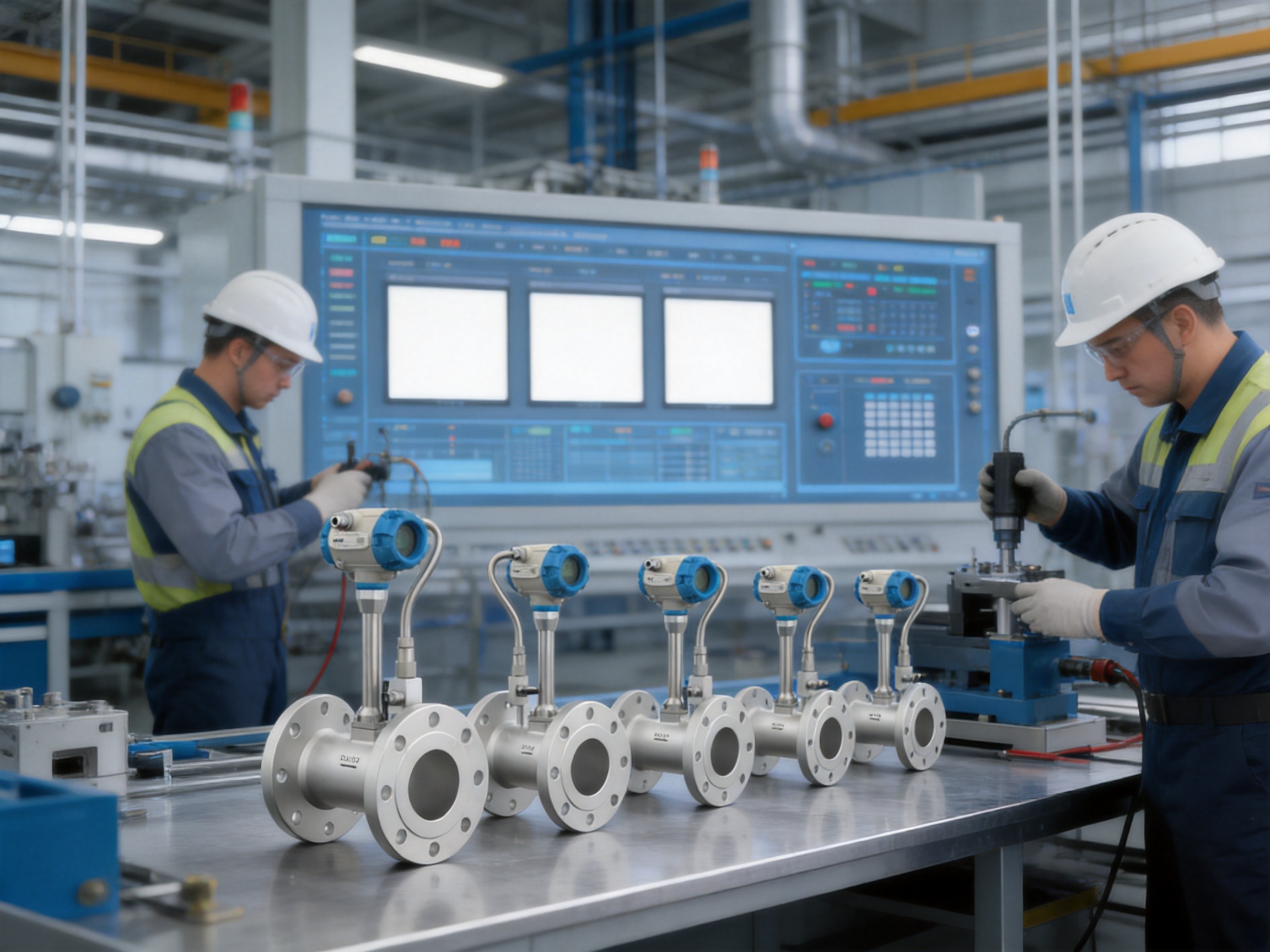
Accurate measurement of steam, compressed air, nitrogen, fuel gas and other industrial media is essential for controlling production costs, improving energy efficiency and maintaining stable process performance. In many plants, measuring only the operating volume of a gas or steam stream is not sufficient. The density of these media changes with temperature and pressure, meaning that the same operating volume can represent very different mass quantities or standard-condition volumes. A reliable measurement system must therefore account for changing process conditions.
The MA80T-TP Series Temperature/Pressure Compensation Vortex Flowmeter is designed for this requirement. Based on the Kármán vortex street principle, it combines vortex flow measurement with integrated temperature measurement and pressure compensation. The converter can calculate operating volumetric flow, standard volumetric flow and mass flow according to the configured medium and reference conditions. This makes the instrument suitable for steam networks, compressed-gas systems, utility metering, energy management and industrial process control.
Manufactured by Jiangsu Vner Electronic Technology Co., Ltd., the MA80T-TP Series benefits from the company’s experience in industrial flow measurement, in-house calibration, engineering-based product selection and automated manufacturing. Its no-moving-parts design, flexible process connections, multiple output options and diagnostic functions provide a practical alternative to conventional mechanical meters and uncompensated flowmeters.
Why Temperature and Pressure Compensation Matter
Flow measurement is often divided into three basic quantities: operating volumetric flow, standard volumetric flow and mass flow. Operating volumetric flow is the volume occupied by a medium under its actual pressure and temperature. Standard volumetric flow is corrected to defined reference conditions. Mass flow represents the actual quantity of material transported through a pipe.
For liquids with relatively stable density, operating volumetric flow may be sufficient for many applications. Gases and steam are different. Their density is strongly influenced by pressure and temperature. If pressure rises, a gas occupies less volume for the same mass. If temperature rises, the gas expands. Steam density also varies according to pressure, temperature and phase condition.
An uncompensated vortex flowmeter measures the volume of the medium at the operating condition. If the process temperature and pressure change significantly, the displayed volume may not provide a consistent basis for energy accounting, utility allocation or production reporting. A temperature and pressure compensated instrument uses additional process information to convert the measured operating volume into a more meaningful standard volume or mass value.
The MA80T-TP Series receives the vortex frequency signal together with temperature and pressure information. Its converter processes these signals in real time and applies the appropriate density or correction relationship for the selected medium. The resulting calculated values can be transmitted to a control system, displayed locally and recorded by a totalizer.
This approach is particularly important for:
• Steam metering between boilers, headers and production units.
• Compressed-air monitoring where pressure fluctuates during plant operation.
• Nitrogen and inert-gas distribution systems.
• Fuel-gas and instrument-air networks.
• Energy balance calculations and utility cost allocation.
• Process lines where mass or standard volume is more useful than actual operating volume.
Operating Principle of the MA80T-TP Series
The flowmeter operates according to the Kármán vortex street principle. When a fluid passes a specially shaped obstruction known as a bluff body or shedder bar, alternating vortices form downstream of the obstruction. These vortices are released from opposite sides of the shedder bar in a repeating pattern.
Within the normal operating range of the meter, the vortex shedding frequency is proportional to the average flow velocity. A piezoelectric sensor detects the pressure fluctuations or mechanical disturbances associated with the vortices. The electronic converter then converts the detected frequency into a flow signal.
The basic relationship may be expressed conceptually as:
Vortex frequency = flow velocity × calibration factor
The calibration factor is related to the geometry of the shedder body and the Reynolds number range of the application. After processing the frequency signal, the converter calculates the operating volumetric flow. When temperature and pressure data are available, the system can then calculate corrected gas or steam values.
The design has no mechanical rotor, impeller or bearing inside the measuring tube. This eliminates many wear mechanisms associated with moving-part meters. It also reduces sensitivity to lubrication problems, bearing failure and mechanical friction. Because the sensor is piezoelectric, it can detect the vortex signal without placing a moving mechanical assembly in the flow path.
The sensor and body are designed for industrial service, with available wetted materials including stainless steel and selected corrosion-resistant alloys. Depending on the model and application, sensor materials may include SS304, SS316L, Hastelloy C, Hastelloy B or titanium.
Integrated Measurement and Compensation Architecture
The MA80T-TP Series combines several measurement functions in one flowmeter system. The primary signal is the vortex shedding frequency. A temperature channel, typically connected to an RTD, provides process-temperature information. A pressure channel accepts the signal from a pressure transmitter or pressure sensor input. The converter combines these values with configured medium data and reference conditions.
The principal calculated variables include:
• Operating volumetric flow.
• Standard volumetric flow.
• Mass flow for configured gases and steam services.
• Accumulated operating volume.
• Accumulated standard volume.
• Accumulated mass.
Different plants may require different reporting bases. A compressed-air system may use standard cubic meters per hour. A steam network may require kilograms per hour or tonnes per hour. A process engineer may need actual operating volume for hydraulic analysis, while an energy manager may need mass flow for boiler efficiency calculations. The converter can be configured to present the variables required by the application.
Temperature and pressure compensation also helps users compare consumption between different points in a utility network. If each measurement point reports only operating volume, data from different pressure and temperature zones may not be directly comparable. Corrected values provide a more consistent basis for production reports, utility billing and energy benchmarking.
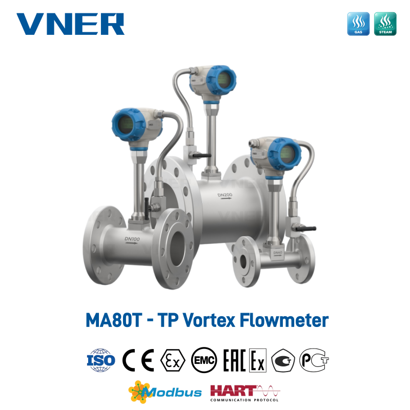
MA80T-TP Series Temperature/Pressure Compensation Vortex Flowmeter
Performance Advantages Compared with Conventional Solutions
Compared with Uncompensated Vortex Flowmeters
A standard vortex flowmeter can provide reliable operating volumetric flow, but it does not automatically account for changes in gas or steam density unless additional instrumentation and calculations are added elsewhere in the control system. The MA80T-TP Series integrates the relevant temperature and pressure inputs into the flow measurement architecture.
This integration reduces the need for separate calculation hardware and can simplify the signal path between the field instrument and the plant control system. It also keeps the flow, temperature and pressure information associated with the same measurement point, improving the practicality of local display and diagnostic review.
For steam and compressed gas applications, the compensated version can therefore provide a more useful measurement output than an uncompensated meter, especially when operating conditions vary during the day or between production campaigns.
Compared with Mechanical Turbine Meters
Turbine meters use a rotating element that can be affected by bearing wear, contamination, viscosity changes and mechanical friction. They may require filtration, maintenance and periodic inspection of the moving assembly. The vortex flowmeter has no moving parts in the flow channel, which can reduce maintenance requirements and improve long-term serviceability.
Vortex meters are also suitable for a broad range of clean or relatively clean gases, steam and compatible liquids. They do not rely on a rotor speed that must remain mechanically stable. For utility steam and compressed-gas systems, the no-moving-parts construction is a valuable advantage when continuous operation and reduced maintenance are priorities.
Compared with Differential-Pressure Flowmeters
Differential-pressure flowmeters calculate flow from the pressure loss produced by an orifice, nozzle or other primary element. They can be widely applied, but the installation often includes impulse lines, valves, manifolds and differential-pressure transmitters. In steam service, impulse-line routing, condensation management and plugging prevention require careful engineering.
The MA80T-TP Series measures vortex frequency directly in the flow body and uses temperature and pressure information for correction. This can reduce the complexity associated with impulse piping. It also avoids the permanent pressure loss commonly associated with restrictive primary elements, although the flowmeter still requires proper sizing and straight-pipe installation.
Compared with Thermal Mass Flowmeters
Thermal mass flowmeters can provide direct mass-flow measurement for selected gases, but their performance may be influenced by gas composition, contamination, humidity, sensor coating and changes in thermal properties. Their calibration is often associated with a particular gas or gas mixture.
The MA80T-TP Series uses vortex frequency as its primary flow signal and calculates mass or standard volume using temperature, pressure and configured medium information. This approach is attractive for steam and for gas networks where the gas composition is known and stable. It also avoids relying on a heated sensing element exposed directly to the process stream.
Compared with Coriolis Mass Flowmeters
Coriolis meters can provide highly accurate direct mass-flow measurement, but they are generally more expensive, heavier and more sensitive to installation and process conditions in larger line sizes. Pressure drop and equipment cost may also become important considerations in high-capacity utility services.
For steam, compressed air and general industrial gases, a compensated vortex meter can offer a practical balance between accuracy, installation cost, line-size flexibility and maintenance requirements. The appropriate choice depends on the required uncertainty, medium, line size, pressure, temperature and project budget. The MA80T-TP Series is especially suited to applications where dependable compensated measurement is required without the full cost and size of a high-end direct mass meter.
Application Range
Steam Measurement
Steam is one of the primary applications for the MA80T-TP Series. The instrument can be used with saturated steam and superheated steam, subject to correct sizing, pressure-temperature limits and installation conditions.
At boiler outlets, the flowmeter can support steam-generation monitoring and boiler-house energy analysis. On main steam headers, it can measure the distribution of steam to different process units. At turbine inlets or major equipment branches, it can assist with energy balance and performance tracking.
In a plant steam network, the ability to calculate compensated mass flow is useful for cost allocation. Individual workshops or production units can be assigned steam consumption based on a consistent measurement basis. This supports internal utility management and helps identify abnormal consumption, leaks or process inefficiency.
For saturated steam, pressure and temperature information can be used to establish the thermodynamic state and corresponding density. For superheated steam, both pressure and temperature are important because the density is determined by the actual thermodynamic condition. The user must configure the medium correctly and operate within the specified range.
Compressed Air and Nitrogen
Compressed-air systems are often among the largest utility consumers in an industrial plant. Air demand changes with production schedules, equipment operation and leakage. Pressure may also fluctuate between the compressor room and remote points of use. A compensated flowmeter can report consumption at standard conditions, making measurements from different parts of the system easier to compare.
Standard-volume data can support compressor optimization, leak surveys and departmental cost allocation. A sudden increase in overnight standard-volume consumption may indicate an air leak or a valve that remains open. A difference between compressor discharge flow and production-area consumption may help identify distribution losses.
Nitrogen and other inert gases are commonly used for blanketing, purging, drying and process protection. The MA80T-TP Series can be applied to clean, single-phase gas systems when the gas properties, operating conditions and installation meet the flowmeter requirements.
Oil and Gas Facilities
Industrial oil and gas facilities use compressed gases, fuel gas, instrument air and utility steam. The flowmeter can support fuel-gas monitoring for burners and furnaces, instrument-air tracking and utility-gas management. Temperature and pressure compensation is important because these networks may operate across different pressure zones and may experience changing demand.
For process applications, the instrument should be selected after reviewing gas composition, pressure, temperature, flow range, potential condensation and required measurement uncertainty. The product is not a universal replacement for custody-transfer meters or specialized multiphase systems. Its strongest application area is clean or relatively clean single-phase gas and steam measurement in industrial utility and process services.
Chemical and Petrochemical Plants
Chemical facilities commonly distribute steam to reactors, reboilers, heat exchangers and tracing systems. Compensated steam measurement helps plant operators understand the energy required by each unit and identify deviations from expected performance.
Compressed nitrogen, inert gases and instrument air are also widely used. A flowmeter with standard-volume output can support utility reporting and production-cost analysis. Where corrosive conditions exist, the availability of SS316L, Hastelloy or titanium sensor options may help engineers select a compatible wetted material, subject to a detailed chemical compatibility review.
Pharmaceutical, Food and Beverage Applications
Pharmaceutical plants may use clean steam for sterilization-in-place systems, autoclaves and process equipment. Flow measurement can support process documentation, qualification activities and utility performance monitoring. Food and beverage facilities use plant steam, compressed air, nitrogen and other utility gases in processing and packaging.
Hygienic, clean-service or regulated applications require careful review of the complete installation, including piping materials, surface requirements, cleaning procedures and validation expectations. The flowmeter should be selected according to the applicable plant standards and process conditions.
HVAC and District Energy
Steam and hot-water distribution systems require reliable sub-metering to support energy management. The MA80T-TP Series is primarily intended for vortex-compatible services, including steam and selected clean liquids. It may be used for industrial HVAC and district-energy measurement where the medium, temperature, pressure and flow range are suitable.
For hot-water services, engineers should confirm that the application falls within the flowmeter’s recommended operating range and that the required density calculation is supported. In applications where thermal energy measurement is required, additional temperature measurement at supply and return points may be necessary.
Product Construction and Materials
The flow body is available in SS304 or SS316L, with customization available upon request for suitable projects. Stainless-steel construction provides a robust base for industrial steam and gas service. The selected material should reflect the medium, pressure, temperature and external environment.
Sensor wetted materials may include SS304, SS316L, Hastelloy C, Hastelloy B and titanium, depending on the specific model. These options help address different levels of corrosion risk. Material selection should not be based only on the name of the medium; moisture content, contaminants, concentration, temperature and pressure can all affect compatibility.
The vortex shedder is a welded, fixed design rather than a rotating assembly. This supports mechanical stability and minimizes the number of components exposed to wear. The piezoelectric sensor detects the vortex signal and sends it to the converter for processing.
Process connections are available in flanged and wafer configurations. Connection standards may include GB, DIN and ANSI, with other standards available on request. This flexibility helps integrate the flowmeter into existing industrial piping systems and international project specifications.
Performance and Operating Limits
Typical volumetric-flow accuracy is up to ±1.0 percent of rate for liquids and approximately ±1.0 percent or ±1.5 percent of rate for gases and steam under calibrated conditions. Actual performance depends on model size, flow velocity, Reynolds number, medium, installation quality, calibration conditions and signal stability.
The typical turndown ratio is up to 1:10 to 1:20, depending on the medium and installation. Engineers should not assume that the maximum turndown is available for every application. Low-flow performance is affected by the ability of the instrument to generate a stable vortex signal, while high-flow performance is limited by pressure loss, vibration, noise and allowable velocity.
Standard temperature capability is up to 250 degrees Celsius, with high-temperature versions available up to 350 degrees Celsius. Pressure ratings can reach up to 4.0 MPa for selected models. Final limits must be confirmed from the applicable datasheet and ordering configuration.
The overall uncertainty of compensated mass flow or standard volume flow is not determined by the vortex sensor alone. It also depends on the accuracy class and installation of the temperature and pressure inputs, the correctness of the fluid configuration, the validity of the density relationship and the stability of the operating range.
| Item | Typical Specification or Option | Engineering Significance |
|---|---|---|
| Measuring principle | Kármán vortex street | Frequency-based flow measurement with no moving parts |
| Primary sensor | Piezoelectric sensor | Detects vortex-related pressure or mechanical fluctuations |
| Measured inputs | Flow frequency, RTD temperature and pressure input | Enables real-time temperature and pressure compensation |
| Calculated values | Operating volume, standard volume and mass flow | Supports process control and energy accounting |
| Typical liquid accuracy | Up to ±1.0% of rate | Applicable under specified calibrated conditions |
| Typical gas and steam accuracy | ±1.0% or ±1.5% of rate | Depends on model, installation and operating range |
| Turndown | Typically 1:10 to 1:20 | Depends on medium, velocity and installation |
| Temperature range | Standard up to 250°C; high-temperature versions up to 350°C | Suitable configuration must be selected for service conditions |
| Pressure rating | Up to 4.0 MPa, model-dependent | Must be checked against the selected body and connection |
| Body materials | SS304 or SS316L | Provides industrial mechanical and corrosion resistance |
| Sensor materials | SS304, SS316L, Hastelloy alloys or titanium | Supports application-specific material selection |
| Process connections | Flanged or wafer | Fits common industrial piping arrangements |
| Communication | 4-20 mA, pulse, optional HART and Modbus RTU | Supports control, monitoring and remote configuration |
Outputs, Communication and Diagnostics
The primary outputs include 4-20 mA and pulse signals. These outputs can be assigned to operating flow, compensated flow or another configured process variable. Pulse output is useful for totalized measurement, while the analog signal can be connected to a distributed control system, programmable logic controller or energy-management platform.
Optional HART and Modbus RTU communication provide access to measured and calculated values. Remote configuration can simplify commissioning and reduce the need to access the local display in difficult field locations. Digital communication can also provide diagnostic information and support maintenance teams during troubleshooting.
The converter can include totalizers for operating volume, standard volume and mass flow. Totalized values are especially important for utility metering because they allow consumption to be reviewed over a shift, day, batch or billing period.
Diagnostic functions may include sensor fault indication, temperature and pressure signal plausibility checks and signal-quality monitoring. These functions help identify problems such as a disconnected RTD, an abnormal pressure input, unstable flow conditions or a weak vortex signal.
When a compensated value appears abnormal, the operator can review the individual input values rather than relying only on the final calculated output. This makes troubleshooting more systematic. A high mass-flow indication could result from a genuine flow increase, a pressure-sensor problem, a temperature-input fault or an incorrect medium configuration. Access to the underlying variables helps distinguish these possibilities.
Installation Requirements
Correct installation is essential for vortex flowmeter performance. The recommended straight-pipe requirement is typically 15 pipe diameters upstream and 5 pipe diameters downstream, although the exact requirement should be confirmed for the selected model and installation arrangement.
Upstream elbows, valves, reducers, expanders, pumps, compressors and partially closed control valves can distort the velocity profile. Swirl and turbulence may affect vortex formation and introduce measurement error. Where the available straight run is limited, a flow conditioner or revised piping arrangement may be considered after engineering review.
The meter should be installed so that the pipe remains full during operation. Gas and steam applications require attention to condensate, drainage and phase stability. For saturated steam, the piping design should prevent excessive liquid accumulation and avoid conditions that create two-phase flow at the meter. Two-phase flow can significantly affect vortex formation and measurement quality.
For compressed gases, the instrument should be protected from liquid carryover, oil contamination and heavy particulate loading. Filters, separators or drains may be required depending on the gas source. The flowmeter itself should not be treated as a substitute for upstream gas conditioning.
Temperature and pressure connections must be installed at appropriate locations and configured with the correct measurement ranges. The pressure input should represent the pressure at the flow measurement point as closely as practical. Excessive distance between the pressure tap and the meter can create an error when pressure changes occur along the line.
Electrical installation should follow the selected output and communication requirements. Shielding, grounding and cable routing should be planned to reduce interference from variable-frequency drives, motors and high-power switching equipment. Outdoor installations may require protection from direct heat, flooding, vibration and corrosive atmospheres.
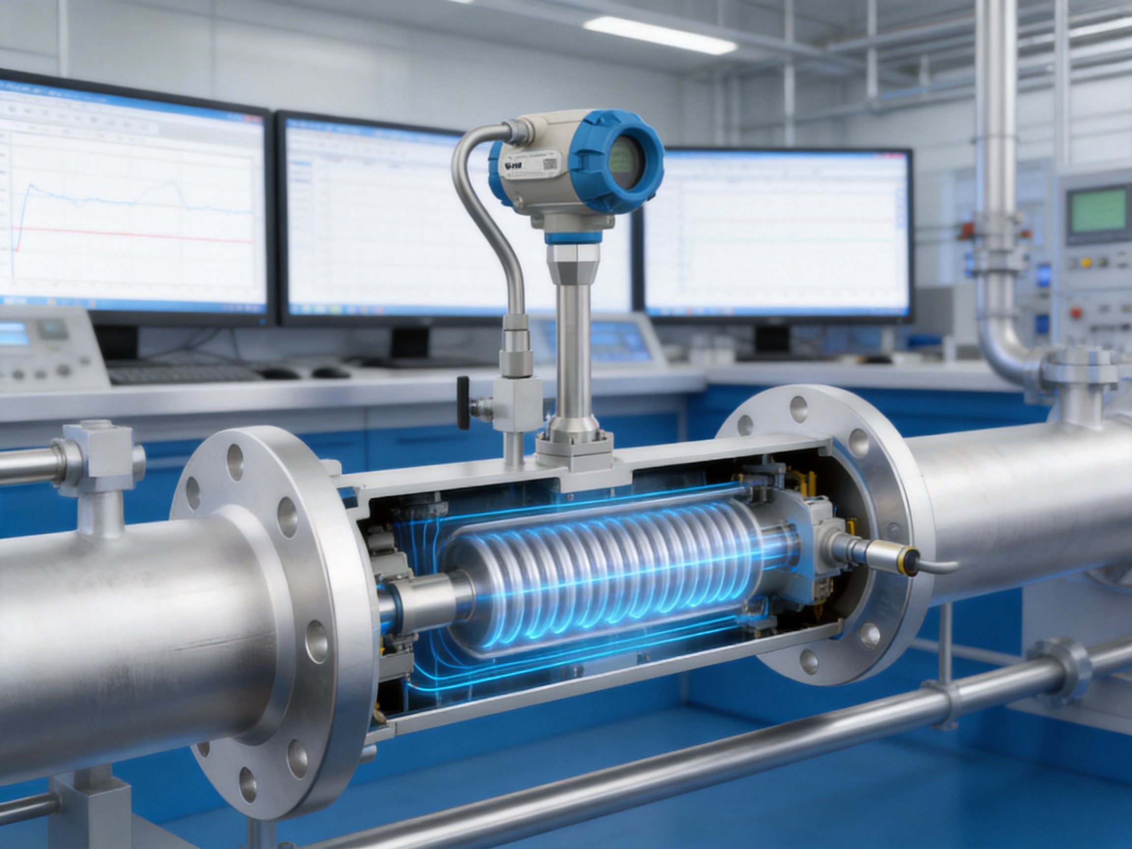
Manufacturing Strengths and Quality Control
The performance of an industrial flowmeter depends not only on its design concept but also on the consistency of its manufacturing process. Shedder geometry, sensor assembly, body machining, welding quality, electronics calibration and final verification all influence measurement stability.
Jiangsu Vner Electronic Technology Co., Ltd. operates three modern plants covering approximately 23,000 square meters and has a technical team of more than 150 people. The company’s product range covers electromagnetic, Coriolis, vortex, swirl, turbine, thermal mass, ultrasonic and rotameter technologies. This broad product base provides practical knowledge across liquid, gas, steam and slurry measurement applications.
The company has delivered more than 2,000 engineering projects in over 30 countries. Experience across oil and gas, petrochemical, polysilicon, power, water and wastewater applications supports application-specific product selection rather than one-size-fits-all supply.
In-house calibration is a key manufacturing strength. Calibration allows the manufacturer to verify the relationship between vortex frequency and flow under controlled conditions. It also supports traceability and helps identify deviations before shipment. For compensated applications, the verification process must consider not only the primary flow signal but also the temperature and pressure input configuration.
Certified quality processes help establish repeatability from one production batch to another. Inspection may include dimensional checks, material verification, pressure testing, electrical testing, sensor signal verification and final functional testing. The exact inspection plan depends on the product configuration and project requirements.
Increasingly automated manufacturing can improve consistency in repetitive production steps while allowing engineers to retain control over application-specific configuration. Automation is particularly valuable for assembly accuracy, process traceability and production documentation.
The company’s engineering-driven sizing and selection approach is another advantage. A vortex meter should not be selected only by pipe size. The actual process flow range, density, viscosity, pressure, temperature, allowable pressure loss, phase condition and required output must be evaluated. Proper sizing helps keep the flow velocity within a range where the vortex signal is stable and the instrument does not operate continuously near its limits.
For EPC contractors and OEM partners, this engineering support can simplify project integration. It allows the meter to be specified with appropriate body material, connection standard, sensor option, pressure input, temperature input, communication protocol and display configuration.
Manufacturing Process for Reliable Field Performance
A typical quality-oriented production route begins with material and component verification. Body material, flange dimensions, sensor components and electronic assemblies are checked against the intended configuration. Correct material identification is especially important for corrosive services and high-temperature applications.
The flow body and shedder assembly must maintain the intended internal geometry. Small changes in the shape, alignment or surface condition of the shedder can influence vortex formation. Controlled machining and inspection help maintain consistency.
Welding and sealing operations require attention to joint integrity and cleanliness. The process must be appropriate for the selected stainless steel or alloy and for the pressure rating of the body. After assembly, pressure testing can help verify mechanical integrity.
The sensor is installed and checked for signal response. Electronic boards and converters are configured according to the requested output, communication and compensation functions. Input channels for RTD and pressure signals must be tested to ensure that the displayed and transmitted values correspond correctly to the connected signals.
Final calibration and functional inspection provide an opportunity to verify the complete instrument. The test should confirm flow response, output scaling, display functions, totalizers, alarm behavior and communication where specified. Documentation can then be prepared for shipment and project records.
Selection Guidance for Engineers
Before ordering an MA80T-TP Series flowmeter, users should prepare a complete process-data sheet. Important information includes:
• Medium name and composition.
• Saturated steam or superheated steam condition.
• Minimum, normal and maximum flow.
• Operating temperature range.
• Operating pressure range.
• Pipe size and material.
• Required process connection and flange standard.
• Allowable pressure loss.
• Required accuracy and measurement purpose.
• Desired output and communication protocol.
• Required temperature and pressure sensor ranges.
• Environmental conditions and area classification.
• Material compatibility requirements.
The minimum and maximum flow values are particularly important. A meter that is oversized may operate below the stable vortex range for much of the year. A meter that is undersized may create excessive velocity, pressure loss, noise or vibration. Selecting the meter based on actual operating conditions rather than nominal pipe diameter improves the probability of long-term success.
For steam, the engineer should identify whether the service is saturated or superheated and provide the expected pressure and temperature range. For compressed gases, the gas composition, moisture level and reference conditions for standard volume should be defined. If the customer requires mass flow, the calculation basis and desired units should be specified before configuration.
Material selection should consider not only corrosion but also temperature cycling, external exposure and cleaning conditions. SS316L may be preferable to SS304 in some environments, while Hastelloy or titanium may be appropriate for certain aggressive media. The final selection should be verified against a chemical compatibility assessment.
Commissioning and Maintenance
Commissioning begins with a mechanical inspection. The installer should confirm that the flow direction matches the arrow on the body, the flange or wafer connection is correctly aligned, gaskets do not protrude into the bore and the pipe is adequately supported. The meter should not be used to correct pipe misalignment by force.
Electrical wiring should be checked against the terminal diagram. The temperature input must match the RTD type and wiring method. The pressure input range and signal type must correspond to the connected transmitter. Output scaling, engineering units, reference conditions and medium configuration should be verified before the process is placed into normal operation.
A controlled start-up is recommended. The system should be observed for abnormal vibration, unstable readings, unexpected pressure loss or signs of liquid carryover. The displayed temperature and pressure should be compared with independent plant instruments when possible.
Because the meter has no moving parts, routine mechanical maintenance is generally limited compared with turbine or positive-displacement meters. Nevertheless, periodic inspection remains important. The flow body should be checked for deposits, corrosion, erosion and damage during planned shutdowns. Wiring, cable glands, grounding and enclosure seals should be inspected in outdoor or high-vibration installations.
Calibration intervals should be based on the application risk, regulatory requirements, operating severity and plant quality system. Steam and gas meters used for internal energy management may follow a different schedule from meters used for commercial allocation or highly controlled process reporting.
When troubleshooting, operators should first review the individual signals. A fluctuating flow indication may result from genuine process pulsation, poor upstream piping, two-phase flow, vibration, electrical interference or a weak signal caused by operation below the recommended range. A compensated output error may originate from the temperature or pressure input rather than the vortex sensor.
Energy Management Benefits
Energy management requires reliable data. Steam, compressed air and nitrogen are often treated as utilities, but they can represent a significant share of operating cost. Installing compensated flowmeters at production units and major distribution branches helps transform utility consumption into measurable performance information.
At the boiler house, mass-flow data can be compared with fuel consumption and boiler output. In a steam distribution network, branch measurements can reveal which areas consume the most energy. At a production line, changes in steam demand can be compared with production volume. In a compressed-air system, standard-volume data can support leakage analysis and compressor scheduling.
Totalized values also support internal cost allocation. Departments can be charged according to measured utility use rather than estimated consumption. This can encourage better operating practices and make energy-saving projects easier to evaluate.
Compensation improves the consistency of these comparisons. If pressure changes from one measurement point to another, standard volume or mass flow provides a more useful common basis than actual operating volume alone.

Frequently Asked Questions
What does the MA80T-TP Series measure?
It measures vortex frequency to determine operating volumetric flow and uses temperature and pressure inputs to calculate compensated standard volume flow and mass flow for configured gases and steam services.
What is the main advantage of temperature and pressure compensation?
Gas and steam density changes with pressure and temperature. Compensation converts the operating measurement into a more consistent mass or reference-condition volume, which is useful for energy accounting, utility allocation and process control.
Can the flowmeter measure both saturated and superheated steam?
Yes, the product is intended for saturated and superheated steam within the applicable temperature, pressure, velocity and installation limits. Correct medium configuration and suitable temperature and pressure inputs are required.
Is the flowmeter suitable for compressed air?
Yes. Compressed air is a typical application. Standard-volume output can help users compare consumption between different pressure zones and identify leakage or abnormal demand.
Does the flowmeter contain moving parts?
No. The measuring body uses a fixed shedder design and a piezoelectric sensor. The absence of a rotor or bearing can reduce mechanical wear and maintenance requirements.
What accuracy can users expect?
Typical volumetric-flow accuracy is up to ±1.0 percent of rate for liquids and approximately ±1.0 percent or ±1.5 percent of rate for gases and steam under calibrated conditions. The final uncertainty of compensated mass or standard volume flow also depends on the temperature and pressure inputs, configuration and installation.
What process connections are available?
Flanged and wafer versions are available. Connection standards include GB, DIN and ANSI, with other standards available on request.
What materials are available?
Body and flange materials include SS304 and SS316L. Depending on the model, sensor wetted materials may include SS304, SS316L, Hastelloy C, Hastelloy B and titanium.
What outputs and protocols are supported?
Primary outputs include 4-20 mA and pulse. HART and Modbus RTU are available as optional digital communication functions. Output assignment can be configured for operating or compensated variables.
What is the typical straight-pipe requirement?
The typical recommendation is 15 nominal pipe diameters upstream and 5 nominal pipe diameters downstream. The final requirement should be confirmed for the selected model and actual piping arrangement.
Can it be installed in a line with limited straight pipe?
Limited straight pipe can affect vortex formation and measurement accuracy. The installation should be reviewed by an engineer. A revised layout or flow conditioner may be considered where appropriate.
How should the pressure input be selected?
The pressure range should cover the minimum and maximum operating pressure while providing suitable measurement resolution. The pressure measurement should represent the pressure at or close to the flowmeter location.
How should a temperature sensor be selected?
The RTD type, temperature range, insertion arrangement and response characteristics should match the process. The sensor must be suitable for the medium, pressure, temperature and installation environment.
Is the instrument suitable for dirty or multiphase media?
The strongest application area is clean or relatively clean, single-phase steam, gas and liquid service. Heavy solids, liquid carryover, severe condensation and multiphase flow can affect vortex formation and should be evaluated before selection.
Why is engineering-based sizing important?
Nominal pipe size alone does not determine whether a vortex meter will perform correctly. Minimum and maximum flow, density, velocity, pressure, temperature and allowable pressure loss must be considered to keep the meter within its recommended operating range.
What manufacturing strengths support product reliability?
The manufacturer operates multiple modern plants, maintains an experienced technical team, performs in-house calibration, applies quality-control procedures and supports automated production and traceability. These capabilities help improve consistency from component inspection through final testing.
Can the flowmeter support an industrial energy-management system?
Yes. Analog, pulse and optional digital communication outputs can provide flow, compensated values and totalizers to a control or energy-management system. The selected integration method depends on the plant architecture.
Conclusion
The MA80T-TP Series Temperature/Pressure Compensation Vortex Flowmeter addresses a common weakness in industrial gas and steam measurement: operating volume alone does not always represent the actual quantity of material delivered. By combining vortex frequency measurement with temperature and pressure inputs, the instrument can provide operating volume, standard volume and mass-flow information from one integrated measurement system.
Its Kármán vortex operating principle, piezoelectric sensing technology and no-moving-parts construction provide a practical foundation for continuous industrial service. Compared with mechanical meters, it can reduce wear-related maintenance. Compared with uncompensated meters, it provides more useful data when pressure and temperature vary. Compared with more complex direct mass meters, it offers a cost-effective option for many steam and clean-gas applications.
Its performance depends on correct sizing, suitable materials, proper installation, stable single-phase flow and accurate temperature and pressure inputs. When these factors are addressed, the flowmeter can support steam distribution, compressed-air management, gas utility monitoring, energy balance, process control and internal cost allocation.
Jiangsu Vner Electronic Technology Co., Ltd. strengthens the product offering through specialized flowmeter manufacturing, in-house calibration, engineering-based selection, multi-technology expertise and project experience across international industrial markets. For EPC contractors, plant operators and OEM partners seeking compensated steam or gas measurement, the MA80T-TP Series provides a flexible and maintainable solution for modern utility and process systems.
References
1. International Organization for Standardization, Industrial Flow Measurement Principles and General Requirements.
2. International Organization for Standardization, Measurement of Fluid Flow in Closed Conduits.
3. International Electrotechnical Commission, Industrial-Process Measurement and Control Equipment Requirements.
4. American Society of Mechanical Engineers, Measurement of Fluid Flow in Pipes and Ducts.
5. International Association for the Properties of Water and Steam, Thermodynamic Properties of Water and Steam.
6. Manufacturer technical information, MA80T-TP Series Temperature/Pressure Compensation Vortex Flowmeter.
7. Manufacturer technical information, Industrial Flow Measurement Product Selection and Application Guidance.
Product: MA80T-TP Series Temperature/Pressure Compensation Vortex Flowmeter


We offer all our products and services at international standards.
Products
Contact Information
-

+86-18652789521
+86-18052582295
+86-0514-83633600 / 83633900 -

+86-0514-83633600 / 83633900
-

shawn@vnerflow.com
info@vnerflow.com -

No. 11 Xingye Road, Chenji Town Industrial Park, Yizheng, Yangzhou, China
