
 0
0
 EN
EN  English
 عربى
عربى Español
 русский
If you need any help, please feel free to contact us
Home / Author / Cai Shurong — After-Sales Project Coordinator / VE13 Hygienic Electromagnetic Flowmeter for Compact Process Lines
VE13 Hygienic Electromagnetic Flowmeter for Compact Process Lines

Accurate flow measurement is essential wherever liquids must be transferred, blended, dosed, cleaned, or monitored under controlled process conditions. In food and beverage production, chemical processing, water treatment, utility skids, and original equipment manufacturer systems, the flowmeter must provide more than a numerical reading. It must maintain dependable accuracy, withstand repeated operating cycles, fit limited installation space, support modern control systems, and remain compatible with the process medium and cleaning method.
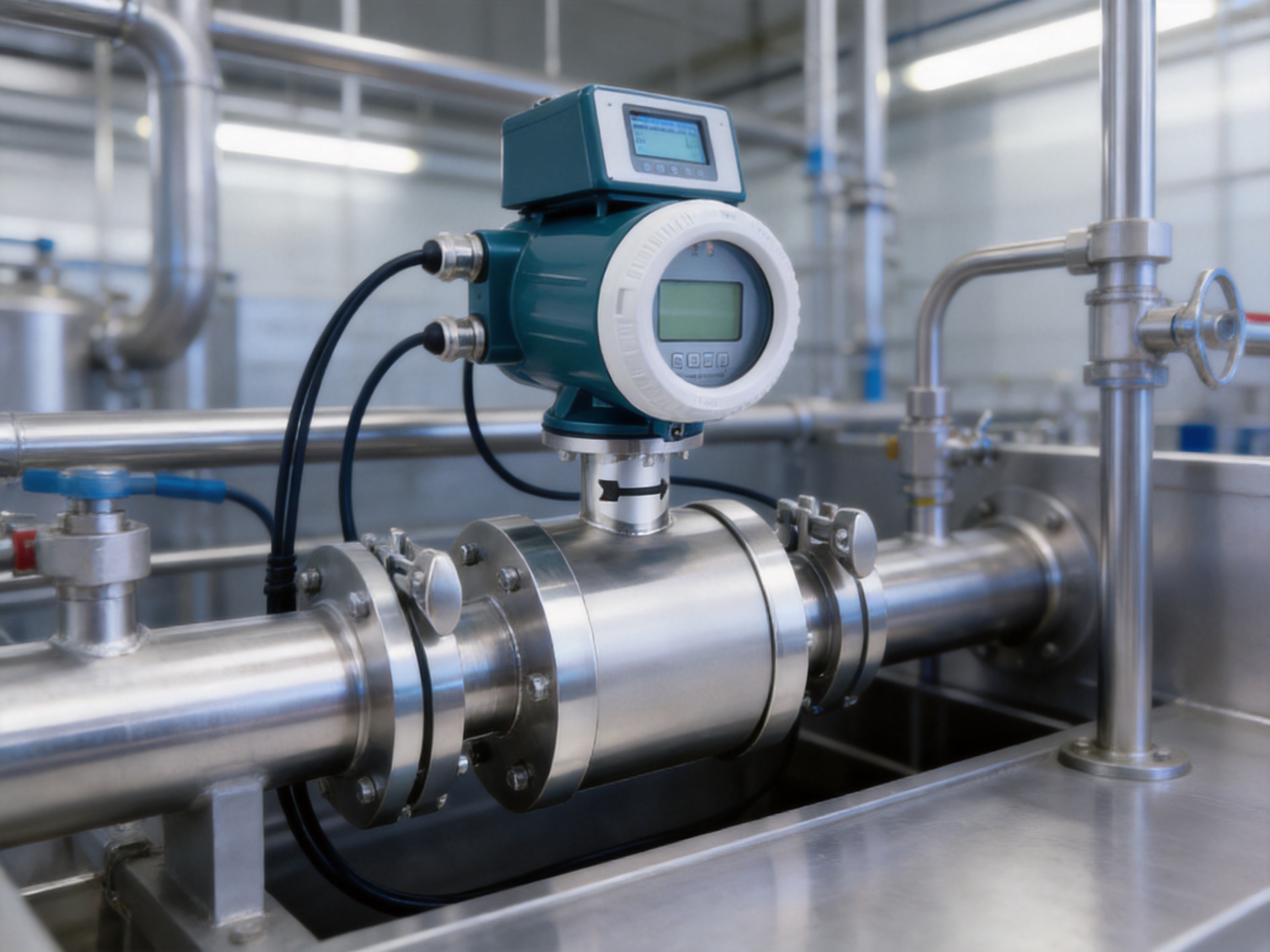
The VE13 Hygienic Electromagnetic Flowmeter is a compact small-bore magmeter developed for these requirements. It measures the volumetric flow of electrically conductive liquids without moving parts or intrusive mechanical components. Its full-bore design minimizes additional pressure loss and reduces the risk of internal blockage. Threaded and Tri-Clamp process connections allow the instrument to be configured for industrial, sanitary, skid-mounted, and equipment-integrated applications.
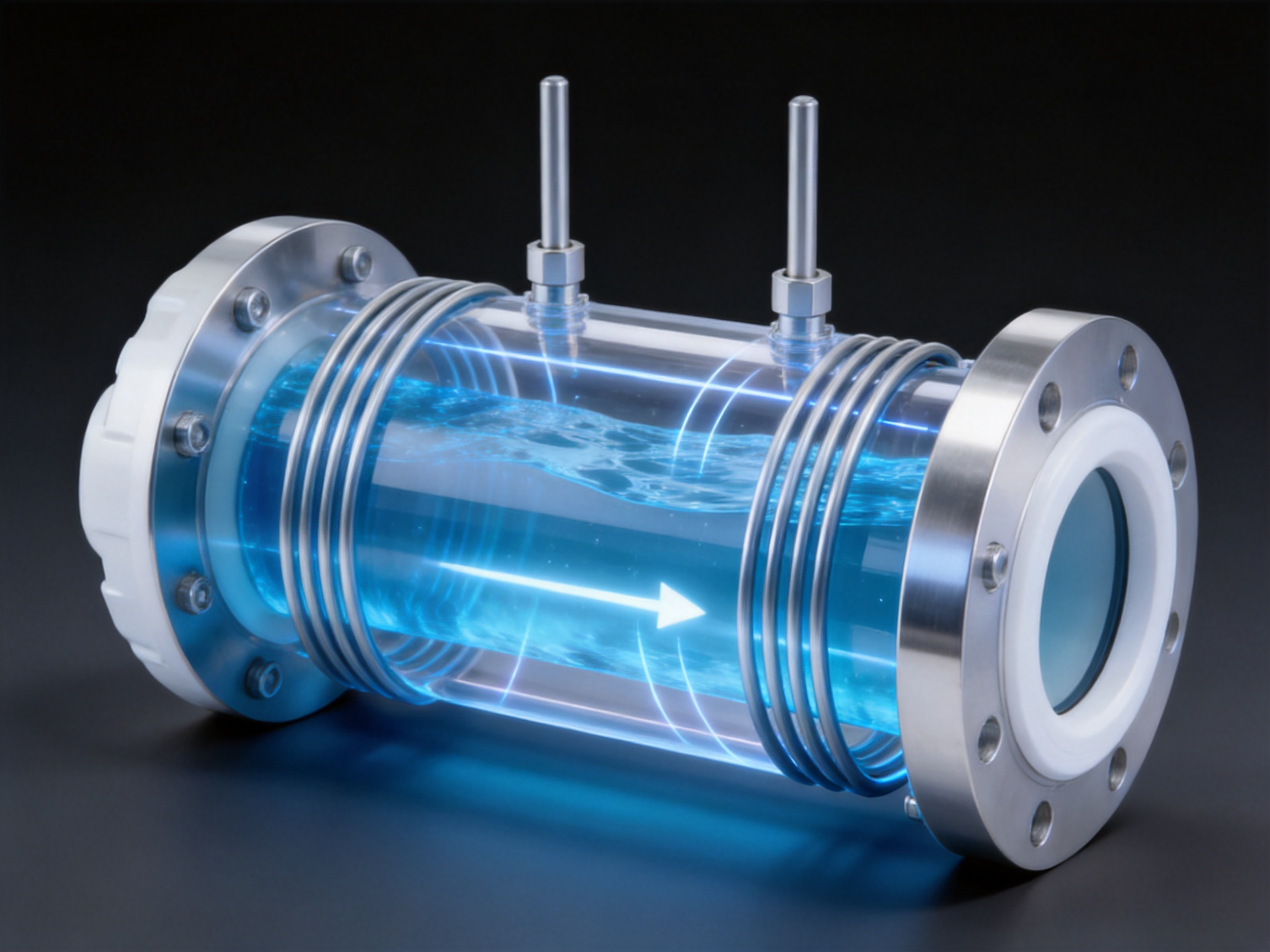
The meter is based on Faraday’s law of electromagnetic induction. When a conductive liquid moves through a magnetic field generated inside the measuring tube, a voltage is induced across the liquid. This voltage is detected by electrodes and processed by the converter to determine flow velocity and volumetric flow rate. Because the measuring principle does not depend directly on mechanical displacement, the VE13 can measure many conductive liquids with stable performance across changing pressure, density, and viscosity conditions.
With an accuracy of up to ±0.5 percent of rate and typical repeatability of 0.16 percent of rate, the VE13 is suitable for process monitoring, transfer measurement, dosing support, and utility services. Its compact construction, stainless-steel body options, hygienic connection choices, digital communication capabilities, and explosion-proof variants make it adaptable to a wide range of industrial requirements.
Why Electromagnetic Flow Measurement Is Suitable for Hygienic Applications
Hygienic process systems place strict demands on equipment surfaces, connection geometry, cleanability, materials, and measurement reliability. A flowmeter installed in such a system must not create unnecessary turbulence, dead zones, contamination risks, or maintenance difficulties. It must also maintain performance when the process includes frequent cleaning, temperature changes, viscous liquids, or repeated start-and-stop operation.
Electromagnetic flowmeters are particularly suitable for conductive liquids because the measuring tube can remain unobstructed. There are no impellers, rotors, gears, bearings, or mechanical sensing elements extending into the flow path. This eliminates many wear mechanisms associated with mechanical flowmeters and prevents moving components from becoming a source of particles or maintenance issues.
The VE13 uses a lined measuring tube and non-intrusive electromagnetic sensing arrangement. The selected lining protects the stainless-steel body from the process medium and provides an electrically suitable and chemically compatible internal surface. FEP and PFA lining options are available depending on the application, temperature, chemical exposure, and cleaning requirements.
Tri-Clamp connections support quick installation and removal in process lines where sanitary assembly, inspection, and cleaning are important. Threaded connections are also available for compact industrial installations and OEM equipment. The appropriate connection should be selected according to the piping standard, pressure rating, cleaning procedure, and applicable hygienic design requirements of the project.
Although the VE13 is designed for hygienic and small-bore applications, hygienic performance always depends on the complete installation. The pipe arrangement, gasket material, connection condition, welding quality, drainage, cleaning-in-place procedure, and process compatibility must be evaluated together. A correctly selected flowmeter can support cleanable and reliable operation, but it cannot compensate for poor piping design or unsuitable cleaning practices.
Operating Principle Based on Faraday’s Law
The fundamental operation of the VE13 is based on Faraday’s law of electromagnetic induction. The converter generates a controlled magnetic field across the measuring tube. As a conductive liquid passes through this field, the charged particles in the liquid move through the magnetic field and generate a small electrical voltage.
The induced voltage is proportional to the average velocity of the liquid. The electronics measure this voltage through electrodes positioned in the measuring tube. After signal conditioning, amplification, filtering, and digital processing, the converter calculates flow velocity and volumetric flow rate. The volumetric flow can then be displayed, transmitted as an analog signal, or converted into a pulse signal for totalization and batching.
The measuring principle offers an important advantage over many mechanical technologies: the flow signal is not generated by a rotating or moving component. This means that the meter does not require an impeller to turn at a speed corresponding to flow. It also avoids mechanical friction, bearing wear, rotor imbalance, and many problems caused by suspended particles or viscous liquids.
For accurate operation, the liquid must have sufficient electrical conductivity. Water, wastewater, many beverages, aqueous solutions, conductive chemical liquids, and numerous slurries are suitable. Non-conductive liquids such as many oils, hydrocarbons, and certain solvent-based products generally require a different flow measurement technology.
When the conductivity requirement is satisfied and the meter is correctly installed, changes in density and viscosity have little direct effect on the measurement principle. This makes the VE13 useful for applications in which liquid composition or temperature changes cause viscosity variation. Nevertheless, the process engineer must still consider the effect of temperature on the liner, electrodes, gaskets, and connection materials.

VE13 Hygienic Electromagnetic Flowmeter
Compact Full-Bore Construction
The VE13 is designed as a compact small-bore electromagnetic flowmeter. Its compact architecture is beneficial for equipment frames, process skids, dosing panels, utility packages, laboratory-scale production systems, and small process lines where installation space is limited. A smaller instrument footprint can simplify pipe routing and reduce the need for extended support structures.
The full-bore measuring tube has no internal obstruction that would significantly restrict the flow. This creates several operational benefits. Pressure loss is practically limited to the natural friction of the pipe and lining rather than a mechanical sensing element. The open passage also reduces the likelihood that fibers, suspended solids, or viscous material will become trapped around an internal mechanism.
Compared with mechanical flowmeters, the VE13 can offer a lower-maintenance solution for conductive liquids that contain suspended particles or experience frequent viscosity changes. A turbine meter, for example, depends on rotor movement and may be more sensitive to contamination, wear, or changes in liquid properties. A positive-displacement meter can provide accurate measurement, but it includes moving parts and may require more attention to lubrication, filtration, and mechanical condition.
Compared with some restrictive primary elements, the electromagnetic design can reduce the permanent pressure loss associated with flow measurement. This can be valuable in transfer lines where pumping energy, available pressure, or product handling conditions must be carefully controlled.
The compact construction does not mean that the meter is limited to simple applications. The converter supports 4-20 mA and pulse outputs, Modbus RS-485 and HART communication, programmable signal processing, and optional explosion-proof configurations. Consequently, the same basic measurement platform can be integrated into local panels, PLC systems, distributed control systems, batch controllers, and plant monitoring networks.
Performance Characteristics
The VE13 provides a stated accuracy of ±0.5 percent of rate. This level of accuracy is appropriate for many industrial transfer, utility, dosing-support, and process monitoring applications. The actual performance achieved in the field depends on meter sizing, liquid conductivity, grounding, installation geometry, calibration, flow profile, and the stability of the process.
Typical repeatability is 0.16 percent of rate. Repeatability describes the ability of the instrument to produce consistent readings when the same operating condition is repeated. High repeatability is particularly useful for batching, comparative process monitoring, recipe control, and detecting changes in production behavior.
The recommended flow velocity range is 0.3 to 10 meters per second. Correct sizing is important because selecting a meter that is too large can result in a low velocity and reduced signal quality, while selecting a meter that is too small can create excessive velocity or pressure loss. Engineering selection should consider the normal, minimum, and maximum flow rates rather than only the nominal pipe size.
Nominal diameters are available from DN10 to DN125, approximately equivalent to 3/8 inch through 5 inches. This range covers many small process lines, sanitary transfer lines, compact utility systems, and OEM assemblies. If the process pipe is larger than the selected meter, suitable reducers and expanders may be considered, provided that the resulting installation maintains an acceptable flow profile and does not create excessive turbulence or air accumulation.
The nominal pressure rating is 1 MPa. The actual allowable pressure depends on the selected connection, liner, temperature, gasket, and configuration. Pressure, temperature, and chemical compatibility should always be verified against the final product specification before ordering.
The medium temperature range is stated as -40 to +200 degrees Celsius depending on configuration. This broad range reflects the availability of different liner, electrode, body, and connection arrangements. It should not be interpreted as a universal operating limit for every version. The highest temperature permitted by the complete assembly, including sanitary seals and process fittings, must govern the application.
Materials and Hygienic Compatibility
The body can be manufactured from stainless steel 304, 316, or 316L. Stainless steel 304 is suitable for many general industrial and utility applications. Stainless steel 316 and 316L provide improved resistance for applications involving more demanding process environments, cleaning chemicals, salts, or hygienic service requirements.
Grade 316L is commonly selected for sanitary process equipment because its low-carbon composition supports improved resistance to certain forms of corrosion associated with welding and aggressive service. However, material selection should be based on actual process chemistry, concentration, temperature, exposure duration, and cleaning regime. No stainless-steel grade is universally resistant to every chemical or operating condition.
FEP and PFA are available as lining materials. These fluoropolymer materials can provide chemical resistance and support applications involving aggressive liquids or elevated temperatures within the approved operating range. The liner also electrically isolates the liquid from the body and forms the internal wetted surface used in the measurement system.
Electrode options include 316L stainless steel, Hastelloy, and titanium. Electrode selection is important because the electrodes are in direct contact with the liquid and must remain chemically stable. 316L is suitable for many water, beverage, and general process applications. Hastelloy may be selected for more aggressive chemical conditions, while titanium can be advantageous in particular corrosive or chloride-containing environments.
For hygienic service, the selected body, liner, electrodes, gaskets, and connections must be treated as one materials system. A chemically compatible liner does not automatically guarantee compatibility of the electrodes or seals. The process documentation should identify the cleaning chemicals, concentration, temperature, flow velocity, exposure frequency, and sterilization conditions where applicable.
Connection Options for Process Integration
The VE13 can be supplied with threaded or Tri-Clamp process connections. Threaded connections are practical for compact industrial lines, utility services, equipment packages, and installations where a sanitary clamp is not required. They can simplify integration into existing pipework and are often convenient for low- to medium-flow process assemblies.
Tri-Clamp connections are widely used in hygienic and food-processing systems. They allow the meter to be removed without cutting pipe or disassembling a flanged joint. When correctly installed with suitable gaskets and clamps, the connection supports quick maintenance and cleaning access. The connection standard, tube dimensions, gasket design, and clamp selection should match the project specification.
DIN and ANSI/ASME connection standards are available according to configuration. Engineering teams should identify the required standard at the selection stage because the mechanical interface affects installation dimensions, gaskets, bolts or clamps, pressure capability, and replacement compatibility.
For small-bore installations, mechanical alignment is especially important. The pipe should be properly supported so that the flowmeter does not carry external pipe loads. Threaded connections should not be forced into alignment, and sanitary clamps should be tightened evenly. Correct alignment helps protect the liner, connection faces, gaskets, and electrodes from unnecessary stress.
The meter should normally be installed in a location where the measuring tube remains full during operation. A full pipe helps prevent air pockets from causing unstable readings. The instrument should not be installed at a high point where gas can collect or immediately downstream of a pump discharge, valve, elbow, or other source of strong flow disturbance unless the installation design has been evaluated.
Signal Processing and Electronics
The VE13 uses microprocessor-based electronics with programmable low-frequency rectangular excitation. This excitation method creates the magnetic field required for measurement while supporting stable signal detection in industrial environments. Digital processing can improve noise immunity, repeatability, and the ability to distinguish the flow signal from electrical interference.
Signal processing is especially important in compact meters because the available electrical signal is relatively small. The converter must amplify the electrode signal while minimizing the effects of electromagnetic interference, grounding problems, cable noise, and process fluctuations. The use of surface-mount components and surface-mount technology supports compact construction and consistent electronic assembly.
Modern electronic manufacturing also contributes to reliability. Consistent component placement, controlled soldering, automated inspection, and documented testing can reduce variation between instruments. A reliable converter is essential because even a mechanically sound sensor cannot provide stable flow measurement if the excitation system, amplifier, or signal-processing circuit is inconsistent.
The 4-20 mA output enables direct connection to common industrial control systems. The signal can represent flow rate, totalized flow, or another configured process variable depending on the application. The pulse output can be used by totalizers, batching systems, counters, and programmable controllers that require a discrete flow-related signal.
Modbus RS-485 communication provides a practical digital interface for remote configuration, data collection, and diagnostics. HART communication can support communication over a conventional 4-20 mA loop where compatible control infrastructure is already installed. These options help reduce the need for local manual adjustments and allow the meter to become part of a wider instrumentation network.
The power supply can be configured for 24 V DC or 220 V AC. This allows the instrument to be matched to control panels, skid packages, plant distribution systems, and OEM equipment. The selected power supply must be confirmed during ordering, especially when replacement units are being installed in an existing panel.
Advantages Compared with Alternative Flowmeter Technologies
Compared with Turbine Flowmeters
Turbine flowmeters use a rotating element that responds to liquid velocity. They can provide good performance in clean, low-viscosity liquids, but their moving components are subject to wear and can be affected by contamination, viscosity, upstream filtration, and changes in flow profile. The VE13 avoids these mechanical concerns because its measuring tube has no rotating parts.
For conductive liquids containing suspended solids, viscous components, or occasional particles, the electromagnetic design can offer reduced maintenance and improved long-term stability. The absence of a rotor also means that there is no mechanical bearing friction to influence the signal at low flow or to create a failure point over time.
Compared with Vortex Flowmeters
Vortex flowmeters detect vortices generated behind a bluff body. They are widely used for gases, steam, and certain clean liquids. However, a vortex meter includes an obstruction in the flow path and may require careful attention to Reynolds number, vibration, flow conditioning, and process pulsation. The VE13 is better suited to conductive liquid service where an unobstructed bore and low pressure loss are priorities.
Unlike a vortex meter, the electromagnetic flowmeter does not rely on vortex shedding frequency. This makes it useful for liquids whose viscosity or flow conditions are not ideal for vortex measurement. It is not a replacement for a vortex meter in gas or steam service, but it offers a more appropriate principle for many conductive liquid applications.
Compared with Coriolis Mass Flowmeters
Coriolis flowmeters directly measure mass flow and can also provide density and temperature information. They are powerful instruments for demanding process applications, but they may be more expensive, heavier, and more complex than necessary for a simple volumetric liquid measurement. The VE13 offers a compact and economical alternative when the required variable is volumetric flow and the liquid is conductive.
The electromagnetic meter also has an open flow path and can be attractive for larger or slurry-containing lines where pressure loss and mechanical complexity must be controlled. A Coriolis meter remains the better choice when direct mass measurement, high-density accuracy, or multiparameter measurement is essential.
Compared with Ultrasonic Flowmeters
Ultrasonic flowmeters can measure liquids without inserting a mechanical element into the flow. Depending on the design, however, they may be sensitive to pipe condition, installation geometry, air bubbles, suspended solids, acoustic properties, or sensor coupling. The VE13 uses a wetted electromagnetic measurement system and can provide a stable solution when conductivity and grounding conditions are suitable.
The choice between technologies should be based on the liquid, pipe, accuracy requirement, maintenance philosophy, and installation environment. The VE13 is especially competitive when the process is conductive, the pipe should remain full bore, and the user wants a compact inline meter with standard industrial outputs.
Compared with Rotameters
Metal tube rotameters provide local visual indication and can be useful for simple flow observation. They generally require the operator to read the display locally and may not provide the same level of digital integration as an electromagnetic flowmeter. The VE13 supports analog, pulse, and digital communication, making it better suited to automated control, remote monitoring, and data logging.
Typical Industrial Applications
Food and Beverage Processing
In beverage and liquid food lines, the VE13 can measure conductive liquids such as process water, sugar solutions, beverages, and selected viscous products. Tri-Clamp connections and stainless-steel construction support integration into hygienic pipe systems. The meter can be used for transfer monitoring, process balance, ingredient handling, utility measurement, and dosing supervision.
Cleaning procedures must be considered carefully. The temperature, concentration, duration, and flow velocity of cleaning solutions should be checked against the selected liner, electrode, gasket, and connection configuration. The instrument should be installed in a position that supports drainage and avoids areas where product or cleaning fluid can remain trapped.
Chemical and General Industry
Conductive chemical raw materials, additives, aqueous solutions, and certain viscous liquids can be measured in small-bore process lines. The availability of Hastelloy and titanium electrodes provides additional flexibility when 316L stainless steel is not appropriate for the process chemistry.
In chemical applications, the selection process should begin with a complete chemical compatibility review. The engineering team should provide the manufacturer with the liquid composition, concentration, temperature, pressure, conductivity, solids content, and cleaning conditions. This information is necessary to select a suitable liner and electrode combination.
Utilities and OEM Skids
Compact equipment packages often have limited space and a high concentration of instruments, valves, pumps, and control components. The VE13 can be integrated into cooling-water circuits, wash-water systems, cleaning-solution lines, water-treatment skids, and other packaged units.
The 24 V DC power option is convenient for control panels and skid systems. The 4-20 mA and pulse outputs simplify connection to programmable controllers, while Modbus RS-485 and HART can provide additional configuration and diagnostic capabilities. Its compact form also supports equipment frames where a larger meter would create difficult piping or maintenance arrangements.
Water and Wastewater Services
Water and wastewater are typically conductive, making electromagnetic measurement a natural choice. The VE13 can be considered for clean water, process water, wash water, and selected wastewater services within its size and pressure range. For liquids containing significant solids, the full-bore design can reduce the risk of obstruction compared with meters that contain internal moving parts.
Air entrainment, incomplete pipe filling, excessive vibration, and poor grounding can affect any electromagnetic flowmeter. These installation factors should be managed through suitable pipe routing, grounding electrodes or rings where required, proper cable practices, and appropriate commissioning.
Technical Specification Summary
| Item | Specification |
| Measuring principle | Electromagnetic measurement based on Faraday’s law |
| Product type | Compact hygienic and small-bore electromagnetic flowmeter |
| Measured media | Electrically conductive liquids and selected slurries |
| Accuracy | ±0.5 percent of rate |
| Typical repeatability | 0.16 percent of rate |
| Flow velocity range | 0.3 to 10 meters per second |
| Nominal diameter | DN10 to DN125, approximately 3/8 inch to 5 inches |
| Process connections | Threaded and Tri-Clamp options |
| Connection standards | DIN and ANSI/ASME options |
| Nominal pressure | 1 MPa |
| Medium temperature | -40 to +200 degrees Celsius, depending on configuration |
| Body materials | Stainless steel 304, 316, and 316L |
| Lining materials | FEP and PFA |
| Electrode materials | 316L stainless steel, Hastelloy, and titanium |
| Protection class | IP65 |
| Outputs | 4-20 mA and pulse |
| Communication | Modbus RS-485 and HART |
| Electrical connections | M20 x 1.5 and 1/2 inch NPT options |
| Power supply | 24 V DC or 220 V AC |
| Explosion protection | Ex d versions available according to configuration |
| Certifications | ISO, CE, and ATEX options depending on model and region |
Manufacturing Strengths and Quality Control
A flowmeter’s field performance depends on more than the published operating principle. Dimensional accuracy, liner installation, electrode positioning, coil consistency, electronic assembly, sealing, calibration, and final inspection all influence the reliability of the completed instrument. For this reason, the manufacturing system behind the VE13 is an important part of its value.
Jiangsu VNER Electronic Technology Co., Ltd. operates as a specialized industrial flowmeter manufacturer in Yangzhou, China. Since 2011, the company has developed and produced electromagnetic, Coriolis, vortex, swirl, turbine, thermal mass, ultrasonic, and rotameter technologies for liquid, gas, and slurry applications.
The company operates modern facilities covering approximately 23,000 square meters across three plants and has a technical team of more than 150 people. This scale supports coordinated engineering, production, quality management, calibration, technical support, and project execution. It also allows the manufacturer to work with EPC contractors, end users, and OEM partners that require repeatable product configurations and documented supply processes.
More than 2,000 engineering projects have been delivered in over 30 countries. Experience across international projects can help the manufacturer understand different connection standards, electrical requirements, industrial environments, documentation practices, and application expectations. It also provides practical feedback from oil and gas, petrochemical, polysilicon, power, water, wastewater, food, and general process industries.
In-house calibration is a major manufacturing strength. Calibration allows the actual instrument response to be checked against controlled reference conditions before shipment. This process helps identify assembly variation, electronic offset, signal instability, and configuration errors. Calibration records also support traceability and give users greater confidence during commissioning and quality audits.
Certified quality processes contribute to consistency throughout production. A controlled manufacturing system can include incoming material inspection, traceable component handling, dimensional verification, coil and electrode checks, liner inspection, electronic testing, pressure testing where applicable, calibration, and final review. The exact inspection plan depends on the model and project requirements, but the principle remains the same: quality should be managed throughout the process rather than evaluated only at the end.
Surface-mount technology and SMD components support compact converter construction. Automated or controlled electronic assembly can improve placement accuracy, solder consistency, and repeatability. Combined with functional testing, this approach helps reduce the risk of intermittent electronic faults and supports long-term operational stability.
Engineering-driven sizing and selection are also important. A flowmeter should not be selected only by matching the nominal pipe diameter. The expected flow range, conductivity, temperature, pressure, liner, electrodes, connection, power supply, communication protocol, and hazardous-area requirements all influence the final configuration. Technical support during selection helps reduce the risk of installing a meter that is mechanically compatible but unsuitable for the actual process.
Configuration and Selection Guidance
The first selection question is whether the liquid is electrically conductive. The conductivity should be confirmed from process data rather than assumed from the liquid name alone. Water-based liquids are often suitable, but conductivity can change with purification, concentration, temperature, or product formulation.
The second question is the flow range. Record the minimum, normal, and maximum flow rates. Use these values to select a nominal diameter that keeps the operating velocity within the recommended range. A meter that is correctly sized for normal operation should also provide acceptable performance during startup, shutdown, reduced production, and maximum throughput.
The third question concerns materials. Provide the process temperature, pressure, chemical composition, concentration, solids content, and cleaning chemicals. The body, liner, electrode, and gasket materials should all be checked. FEP, PFA, 316L, Hastelloy, and titanium are not interchangeable in every service.
The fourth question concerns the connection. Select threaded connections for suitable compact industrial lines and Tri-Clamp connections for applications requiring sanitary clamp installation. Confirm whether the project uses DIN, ANSI/ASME, or another mechanical standard.
The fifth question concerns electrical integration. Confirm whether the system requires 24 V DC or 220 V AC, 4-20 mA, pulse output, Modbus RS-485, HART, or a combination of these features. The control system architecture should also define whether flow, totalized volume, alarms, or diagnostic information must be transmitted.
The final question concerns the installation environment. If the meter is located in a designated hazardous area, an Ex d version may be required. The protection class is IP65, but the enclosure should still be installed away from unnecessary water spray, flooding, excessive vibration, and direct mechanical impact.
Installation Practices for Stable Measurement
The measuring tube should remain full during operation. A full pipe prevents air from passing through the electrodes and causing fluctuating readings. Suitable locations include vertical upward-flow sections or horizontal sections that are continuously flooded. High points, open discharge lines, and locations immediately before a free fall should generally be avoided.
Provide adequate straight pipe where necessary to establish a stable flow profile. The required upstream and downstream lengths depend on the piping arrangement and the degree of disturbance created by valves, elbows, reducers, pumps, and tees. When space is limited, the installation should be reviewed carefully rather than assuming that a compact meter is unaffected by all upstream conditions.
Grounding is essential for electromagnetic measurement. The liquid, meter body, and control system must have a suitable electrical reference. Grounding rings or grounding electrodes may be needed when the pipe material is non-conductive or when the connection arrangement does not provide a reliable reference. Installation should follow the manufacturer’s wiring and grounding instructions.
Keep the signal cable away from strong electromagnetic sources where practical. Variable-frequency drives, large motors, transformers, high-current cables, and switching equipment can introduce interference if signal routing is poorly designed. Shielding, grounding, cable separation, and correct termination help preserve signal quality.
Do not use the flowmeter as a structural support for unsupported pipework. External pipe stress can damage connections or create alignment problems. Install supports close enough to prevent vibration and mechanical loading while leaving access for inspection and maintenance.
After installation, verify the direction of flow, power supply, output scaling, zero stability, communication settings, alarm limits, and totalizer configuration. Commissioning should be conducted with the process operating at representative conditions whenever possible.
Maintenance and Long-Term Reliability
The absence of moving parts significantly reduces routine mechanical maintenance. There are no bearings to lubricate, rotors to replace, or gears to inspect. Nevertheless, periodic inspection remains valuable. Check the housing, cable glands, process connections, gaskets, grounding, display or control signals, and external signs of corrosion or mechanical damage.
In hygienic applications, inspect the Tri-Clamp connection and gasket condition during planned maintenance. A damaged or incorrectly installed gasket can create leakage, contamination risk, or a difficult-to-clean joint. The cleaning procedure should be checked against the materials and temperature limits of the complete assembly.
If the process contains deposits, the internal liner and electrodes may require inspection. Although the full-bore design reduces obstruction risk, heavy deposits or non-conductive coatings can affect the electrode signal. The correct cleaning method depends on the product and liner material. Abrasive tools or unsuitable chemicals should not be used without confirming compatibility.
Electrical inspection should include verification of supply voltage, cable integrity, shielding, grounding, output loop condition, and communication status. Unstable readings are not always caused by the meter itself. Empty pipe conditions, air bubbles, poor grounding, electrical interference, incorrect configuration, and process conductivity changes should all be considered during troubleshooting.
When a process is modified, review the flowmeter configuration again. Changes in cleaning chemistry, product concentration, maximum temperature, pressure, or flow range can affect the suitability of the original liner, electrodes, gaskets, and calibration settings.
Application Example: Beverage and Liquid Food Transfer
Consider a stainless-steel beverage transfer line equipped with Tri-Clamp connections. The line carries syrup, finished beverage, or process water between a preparation vessel and a filling or blending system. The flowmeter must fit a compact pipe rack, tolerate repeated operating cycles, provide a control signal to the batching system, and support cleaning procedures defined by the plant.
The VE13 can be configured with a stainless-steel body, a suitable FEP or PFA liner, and electrode material selected for the product and cleaning solution. The 4-20 mA output can transmit the instantaneous flow rate to a controller, while the pulse output can support volume totalization. Modbus or HART can be used where remote configuration or diagnostics are required.
During selection, the plant should identify the minimum and maximum transfer rate, liquid conductivity, operating temperature, cleaning temperature, pressure, product viscosity, and required connection standard. If the liquid includes suspended ingredients or particles, the full-bore design can reduce the mechanical restrictions associated with a rotor-based meter.
Installation should allow the meter to remain full and should avoid locations where air can collect. The pipe should be supported independently, and the grounding arrangement should be checked before commissioning. After the initial test, the plant can compare the meter reading with a reference volume or calibrated transfer procedure.
This example illustrates why the VE13 should be selected as part of a complete application system. Hygienic performance results from the combination of material compatibility, connection design, piping arrangement, cleaning practice, and instrument configuration.
Integration with Automation Systems
Industrial automation systems increasingly require instruments that can provide both a conventional control signal and digital information. The VE13 supports this approach through its 4-20 mA output, pulse output, Modbus RS-485 communication, and HART communication options.
The 4-20 mA signal is widely accepted for process control because it is robust, easy to diagnose, and compatible with many PLC and DCS input modules. A live-zero signal allows the control system to distinguish a low process value from a broken or disconnected circuit. The output range can be scaled according to the expected operating flow and the needs of the control strategy.
The pulse output is useful when the system must count a defined volume. Applications include batching, transfer totals, utility consumption, and production reporting. Pulse scaling must be configured carefully so that the receiving controller interprets the signal correctly and does not exceed its maximum input frequency.
Modbus RS-485 can provide access to measurement values, status information, configuration parameters, and diagnostic data depending on the selected communication implementation. HART allows digital communication over a current loop and can be useful in plants that already use HART-enabled asset management or maintenance systems.
Remote communication can reduce the need to open an enclosure or access a difficult installation location. It can also support instrument standardization, parameter backup, commissioning, and maintenance documentation across multiple process lines.
Explosion-Proof and Environmental Options
Ex d explosion-proof versions are available for applications that require an explosion-protected enclosure. Hazardous-area selection must follow the classification, gas or dust group, temperature class, certification region, and installation rules applicable to the site. The meter configuration, cable glands, wiring method, and associated equipment must be evaluated as a complete system.
The standard protection class is IP65. This indicates protection against dust ingress sufficient for the specified enclosure rating and protection against water jets from applicable directions. IP65 does not mean that the meter can be submerged or exposed indefinitely to high-pressure washdown beyond the approved conditions. Installation should prevent water accumulation around cable entries and covers.
For outdoor or harsh industrial installations, consider temperature cycling, solar exposure, condensation, vibration, corrosive atmosphere, and accessibility. Protective mounting or a suitable instrument enclosure may be required. The product should be installed according to the environmental limitations stated for the selected configuration.
How the Product Supports Lifecycle Value
Lifecycle value includes purchase cost, installation effort, energy consumption, maintenance, downtime, calibration, replacement, and integration. The VE13 can support lifecycle efficiency through its unobstructed bore, non-mechanical sensing system, compact design, and standard communication options.
Low additional pressure loss can help reduce the hydraulic penalty associated with measurement. In a continuously operating system, even modest pressure loss can influence pump selection and energy consumption. The actual energy benefit depends on the complete piping system and should be calculated during project design.
The absence of moving parts reduces the number of mechanical wear items. This can simplify preventive maintenance and reduce the likelihood of a rotor or bearing failure. Stable repeatability also helps operators identify process deviations before they develop into larger production problems.
Standard outputs and communication interfaces can reduce integration effort. A meter that connects easily to existing PLC, DCS, batch, or monitoring systems may require fewer additional signal converters and less custom programming. The compact construction can also reduce skid size and simplify spare-parts planning.
Finally, manufacturer support, calibration capability, documented quality processes, and product-family experience contribute to long-term serviceability. Users can obtain related electromagnetic, Coriolis, vortex, swirl, turbine, thermal mass, ultrasonic, and rotameter technologies from a manufacturer with broad flow measurement experience, which may simplify vendor coordination for multi-technology projects.
Frequently Asked Questions
What liquids can the VE13 measure?
The VE13 is intended for electrically conductive liquids and selected slurries. Examples include water, beverages, sugar solutions, cleaning solutions, conductive chemical liquids, and certain viscous products. Conductivity should be confirmed before selection, particularly for purified liquids, concentrated products, or liquids containing non-conductive solvents.
Can the VE13 measure non-conductive oil?
Standard electromagnetic flow measurement requires sufficient electrical conductivity. Many oils and hydrocarbon liquids are not suitable. A different technology, such as turbine, Coriolis, positive displacement, or ultrasonic measurement, may be more appropriate depending on the process requirements.
Does the VE13 have moving parts?
No. The measuring tube has no rotating or moving sensing parts. The flow signal is generated electromagnetically through the interaction between the conductive liquid and the applied magnetic field.
What is the accuracy of the VE13?
The stated accuracy is ±0.5 percent of rate. Typical repeatability is 0.16 percent of rate. Actual performance depends on correct sizing, installation, grounding, conductivity, calibration, and process stability.
What are the available sizes?
Nominal diameters range from DN10 to DN125, approximately 3/8 inch to 5 inches. The correct size should be selected using the minimum, normal, and maximum flow rates rather than pipe diameter alone.
Is the meter suitable for hygienic process lines?
It can be suitable for hygienic applications when configured with appropriate stainless-steel materials, liner, electrodes, gaskets, and Tri-Clamp connections. The complete installation must also satisfy the user’s cleaning, drainage, material, and sanitary design requirements.
What outputs are available?
The VE13 supports 4-20 mA and pulse outputs. Modbus RS-485 and HART communication options are also available depending on the configuration.
Can it be connected to a PLC or DCS?
Yes. The 4-20 mA output is suitable for common analog input modules, and the pulse output can be connected to totalizers or batch controllers. Modbus RS-485 and HART can provide additional digital integration.
What power supplies are available?
The instrument can be configured for 24 V DC or 220 V AC. The required power supply should be specified during ordering and checked against the control panel or equipment package design.
What is the maximum medium temperature?
The stated medium temperature range is -40 to +200 degrees Celsius depending on configuration. The actual limit is determined by the liner, electrodes, body, gasket, connection, and other selected components.
Can the meter be used in hazardous areas?
Ex d explosion-proof versions are available for designated hazardous locations. The exact certification and installation requirements must be verified according to the site classification and applicable regional regulations.
What causes unstable electromagnetic flow readings?
Common causes include an empty or partially filled pipe, air bubbles, insufficient conductivity, poor grounding, electrical interference, incorrect flow direction, unsuitable installation geometry, deposits on the electrodes, or an improperly configured converter.
How should the flowmeter be sized?
Provide the minimum, normal, and maximum flow rates, process pipe size, liquid conductivity, temperature, pressure, viscosity, solids content, connection standard, and required outputs. The meter should operate within the recommended velocity range of 0.3 to 10 meters per second.
Does the meter create significant pressure loss?
The full-bore design has no internal mechanical obstruction and introduces practically no additional pressure loss beyond the natural hydraulic effects of the pipe and lining.
Why are electrode materials important?
Electrodes contact the process liquid and must resist corrosion and chemical attack. The available 316L stainless steel, Hastelloy, and titanium options allow the meter to be adapted to different liquid and cleaning conditions.
Conclusion
The VE13 Hygienic Electromagnetic Flowmeter combines a proven Faraday-law measurement principle with a compact full-bore design for conductive liquid service. Its lack of moving parts reduces mechanical wear and obstruction risk, while its measurement is largely independent of pressure, temperature, density, and viscosity within the specified operating conditions.
Threaded and Tri-Clamp connections support flexible process integration. Stainless-steel body options, FEP and PFA liners, and multiple electrode materials help users match the instrument to hygienic, chemical, utility, and OEM applications. A flow velocity range of 0.3 to 10 meters per second, accuracy of ±0.5 percent of rate, and typical repeatability of 0.16 percent of rate provide a useful combination of performance and practicality for small-bore process lines.
The instrument’s 4-20 mA and pulse outputs, Modbus RS-485 and HART communication, 24 V DC or 220 V AC power options, IP65 protection, and available Ex d configurations make it suitable for modern industrial automation systems. Its advantages over mechanical and restrictive technologies are most evident when the liquid is conductive, the process requires a clear flow path, maintenance should be minimized, and compact installation is important.
These product benefits are supported by the manufacturer’s broader engineering and production capabilities. Modern facilities, a specialized technical team, in-house calibration, certified quality processes, automated electronic assembly practices, international project experience, and application-focused selection support contribute to repeatable product quality and reliable project execution.
For the best result, users should treat the VE13 as part of a complete measurement system. Correct sizing, material compatibility, full-pipe installation, grounding, signal wiring, cleaning practice, and commissioning are essential. When these factors are properly addressed, the VE13 can provide a durable and efficient flow measurement solution for hygienic and industrial conductive-liquid applications.
References
1. Faraday, M. Experimental Researches in Electricity. Foundational work related to electromagnetic induction and the operating principle of electromagnetic flow measurement.
2. International Electrotechnical Commission. Electromagnetic Compatibility Requirements for Industrial Measurement and Control Equipment.
3. International Organization for Standardization. Quality Management Systems: Requirements for Controlled Manufacturing and Traceable Production Processes.
4. International Organization for Standardization. Stainless Steels for General and Hygienic Industrial Applications.
5. American Society of Mechanical Engineers. Process Piping Design and Connection Practices.
6. International Organization for Standardization. Hygienic Design Principles for Food Processing Equipment and Process Installations.
7. International Electrotechnical Commission. Degrees of Protection Provided by Enclosures for Electrical Equipment.
8. International Electrotechnical Commission. Equipment and Installation Requirements for Electrical Apparatus in Potentially Explosive Atmospheres.
9. Industrial Instrumentation Engineering Practice. Flowmeter Sizing, Installation, Grounding, Calibration, and Signal Integration Guidance.
10. Manufacturer technical documentation for compact electromagnetic flowmeters, hygienic process connections, liner selection, electrode materials, and converter configuration.
Product: VE13 Hygienic Electromagnetic Flowmeter

We offer all our products and services at international standards.
Products
Contact Information
-

+86-18652789521
+86-18052582295
+86-0514-83633600 / 83633900 -

+86-0514-83633600 / 83633900
-

shawn@vnerflow.com
info@vnerflow.com -

No. 11 Xingye Road, Chenji Town Industrial Park, Yizheng, Yangzhou, China
