
 0
0
 EN
EN  English
 عربى
عربى Español
 русский
If you need any help, please feel free to contact us
Home / Author / Ding Yuchun — Overseas After-Sales Support Engineer / Insertion Electromagnetic Flowmeters for Large-Diameter Industrial Pipelines
Insertion Electromagnetic Flowmeters for Large-Diameter Industrial Pipelines
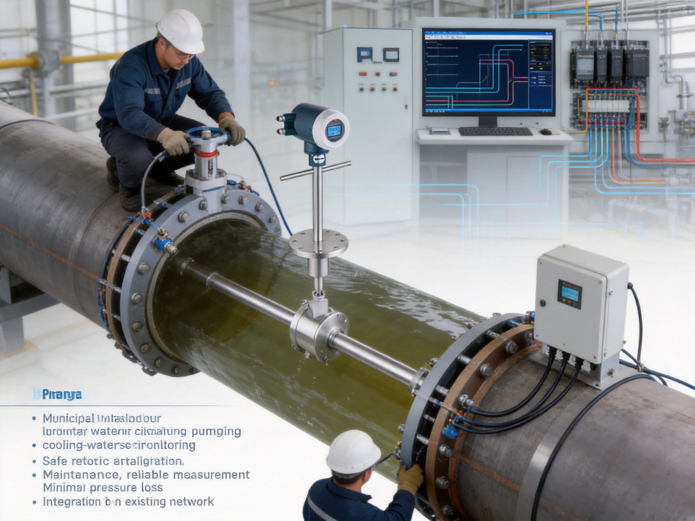
Large-diameter pipelines are essential to municipal water systems, industrial utilities, irrigation networks, mining operations, pulp and paper plants, and many other process industries. Yet measuring flow accurately in these pipelines can be difficult. A full-bore electromagnetic flowmeter may require substantial investment, extended shutdowns, heavy lifting equipment, complex civil work, and a large installation footprint. In some applications, the cost and disruption associated with replacing or modifying the pipeline can be greater than the cost of the measuring instrument itself.
The VE15 Insertion Electromagnetic Flowmeter is designed to address this challenge. It is a plug-in electromagnetic flowmeter for electrically conductive liquids in pipelines from DN200 to DN4000, equivalent to approximately 8 to 160 inches. Instead of occupying the complete cross-section of the pipe, the VE15 uses an insertion probe installed through a suitable fitting or mounting assembly. The probe measures the local liquid velocity, while the converter calculates the volumetric flow rate using the measured velocity and the known internal pipe diameter.
This design offers a practical alternative to conventional full-bore meters in large transmission mains and process lines. It reduces material requirements, simplifies retrofit installation, minimizes pressure loss, and allows flow measurement to be introduced into existing infrastructure with less interruption. At the same time, the instrument retains the principal advantages of electromagnetic measurement: no moving parts, no mechanical obstruction in the flow path, excellent suitability for dirty liquids, and measurement that is largely independent of density, viscosity, pressure, and temperature within the specified operating range.
The following article examines the operating principle, construction, performance, installation requirements, industrial applications, manufacturing strengths, and selection considerations of the VE15 Insertion Electromagnetic Flowmeter.
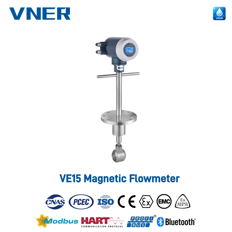
VE15 Insertion Electromagnetic Flowmeter
1. The Measurement Challenge in Large-Diameter Pipelines
Flow measurement in a small process line is usually straightforward. A full-bore meter can be selected, the pipeline can be isolated, and the instrument can be installed using standard flanges. Large pipelines create a different set of engineering and commercial constraints. A DN800, DN1200, or DN2000 line contains a substantial volume of liquid and may be a critical part of a water, cooling, slurry, or production network. Taking such a line out of service may affect an entire plant or a large population of users.
Full-bore meters for large pipelines are also physically large and heavy. Their transportation, lifting, alignment, support, and commissioning requirements increase with nominal pipe size. The associated flanges, gaskets, supports, chambers, and civil structures can add considerably to the total project cost. In buried pipelines, the installation may require extensive excavation and reconstruction. In operating plants, access limitations can make the installation of a large meter especially challenging.
A second issue is pressure loss. Any device that introduces a permanent obstruction into the pipe can consume pumping energy and influence the hydraulic characteristics of the system. Although many full-bore electromagnetic meters have a smooth internal lining and relatively low pressure loss, an insertion design can reduce the amount of material placed inside the pipeline and therefore provide a highly economical solution for line monitoring, balancing, and water allocation.
Large systems frequently need multiple measurement points rather than a single custody-transfer meter. A municipal network may require measurements at transmission mains, distribution branches, pumping stations, reservoirs, and outfalls. A factory may need to monitor flow to cooling consumers, treatment units, and process areas. Installing a full-bore meter at every point can be expensive. Insertion technology makes wider deployment more practical, especially when the primary objective is reliable operational data, system balancing, leak detection, or energy optimization.
2. Product Overview
The VE15 is an insertion or plug-in electromagnetic flowmeter intended for large-diameter pipelines carrying electrically conductive liquids. Its specified nominal pipe size range is DN200 to DN4000. Depending on the configuration, the instrument may be supplied with flanged or plug-in mounting arrangements and with different converter, enclosure, communication, lining, electrode, and protection options.
The meter is suitable for a broad range of conductive media, including raw water, treated water, wastewater, cooling water, process water, conductive chemical solutions, viscous liquids, pulp, sludge, and selected slurries. It is not intended for nonconductive liquids unless the application is otherwise confirmed by the manufacturer. Conductivity, pipe condition, installation geometry, grounding, and the properties of the process medium must be reviewed during selection.
The VE15 combines a stainless steel 304 body with a PTFE lining and measuring electrodes available in 316L stainless steel or Hastelloy, depending on the chemical and process requirements. The specified pressure rating is up to 1.6 MPa, while the medium temperature range can extend from approximately -40 to +200 °C depending on the selected configuration. Protection options include IP65, IP67, and IP68 versions. Explosion-proof Ex d configurations are also available for designated hazardous areas when the complete installation meets the applicable requirements.
| Parameter | Typical VE15 Specification | Engineering Significance |
|---|---|---|
| Product type | Insertion electromagnetic flowmeter | Designed for large-diameter lines and retrofit applications |
| Nominal pipe size | DN200 to DN4000 | Covers large transmission and process pipelines |
| Measuring principle | Faraday’s law of electromagnetic induction | Measures conductive liquid velocity without moving parts |
| Measured media | Electrically conductive liquids, slurries, pulp, and sludge | Suitable for many dirty and difficult liquid services |
| Flow velocity range | 0.5 to 8 m/s | Supports low-flow monitoring and higher-capacity operation |
| Accuracy | ±1.0% or ±1.5% of rate, model-dependent | Selection should reflect the required measurement duty |
| Repeatability | ±0.33% or ±0.5% | Supports stable trending, balancing, and control |
| Nominal pressure | Up to 1.6 MPa | Must be checked against actual line pressure and transients |
| Body material | Stainless steel 304 | Provides a robust mechanical structure |
| Lining | PTFE | Supports chemical resistance and electrical insulation |
| Electrodes | 316L stainless steel or Hastelloy | Allows adaptation to different liquid chemistries |
| Outputs | 4–20 mA and pulse | Compatible with common control and totalizing systems |
| Communication | Modbus RS-485, HART, and Profibus options | Enables connection to PLC, DCS, SCADA, or asset systems |
| Power supply | 24 V DC or 220 V AC | Fits common industrial electrical architectures |
3. How Electromagnetic Measurement Works
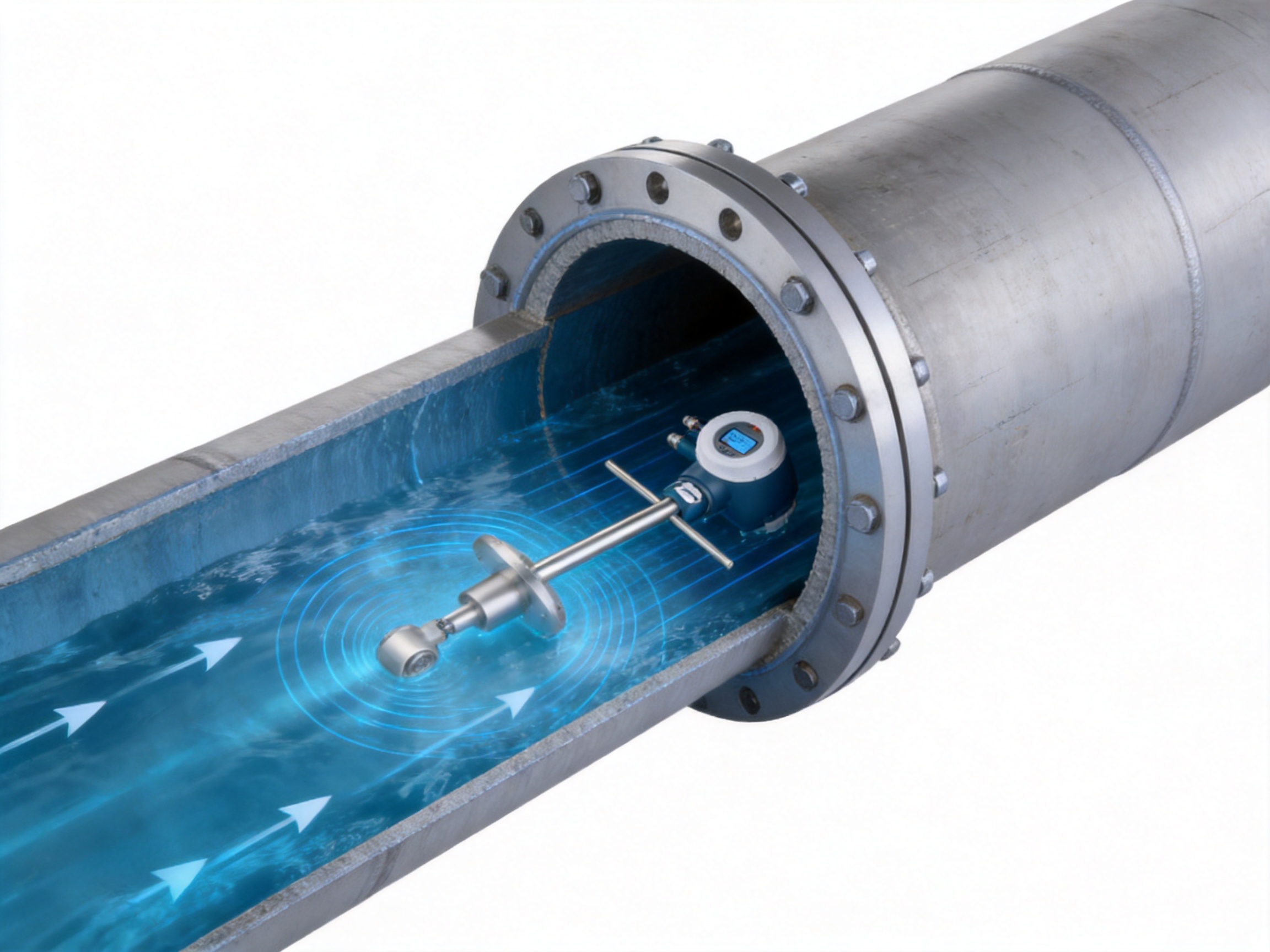
The VE15 operates according to Faraday’s law of electromagnetic induction. When an electrically conductive liquid moves through a magnetic field, a voltage is induced in the liquid. The magnitude of this voltage is proportional to the velocity of the liquid moving through the magnetic field. Measuring electrodes positioned in the probe detect this small electrical signal.
The converter generates the excitation required to establish the magnetic field. It then receives, amplifies, filters, and processes the electrode signal. Because the relationship between induced voltage and velocity is well established, the electronics can determine the liquid velocity at the measurement point. The programmed pipe diameter and meter calibration data are then used to calculate volumetric flow.
In simplified form, the volumetric flow rate is related to the average velocity and the cross-sectional area of the pipeline. For an insertion meter, correct positioning is particularly important because the probe measures velocity at a defined location rather than directly averaging the entire pipe cross-section. The installation design, insertion depth, orientation, pipe geometry, and flow profile all influence the relationship between the measured local velocity and the average velocity in the pipeline.
This is why an insertion electromagnetic flowmeter should not be treated as a simple drilling-and-mounting device. The instrument can provide stable and repeatable results when installed according to the application requirements, but engineering attention must be given to straight runs, elbows, reducers, valves, pumps, partially filled conditions, pipe lining, grounding, and the location of the probe in relation to the hydraulic profile.
Electromagnetic measurement has an important advantage for water, wastewater, pulp, sludge, and slurry services: there are no bearings, impellers, gears, or rotating shafts exposed to the medium. This eliminates mechanical wear associated with moving components and reduces the risk of blockage caused by internal mechanical structures. The absence of a traditional flow obstruction also helps keep additional pressure loss low.
Low-Frequency Excitation and Signal Stability
The VE15 uses microprocessor-based electronics with programmable low-frequency rectangular excitation. This type of excitation supports stable signal processing and helps improve resistance to electrical interference and process noise. It also contributes to reliable measurement when the liquid contains suspended solids or when the installation operates in an electrically demanding industrial environment.
Modern signal processing is essential because the voltage generated by electromagnetic induction is relatively small. The converter must distinguish the useful flow signal from electrical noise, electrode polarization, grounding disturbances, pump interference, and other influences. A carefully designed excitation and processing system can improve repeatability and maintain stable output under changing operating conditions.
4. Main Advantages Over Conventional Large-Bore Metering Solutions
4.1 Lower Installation Burden
The most visible advantage of an insertion meter is the reduced physical size compared with a full-bore meter of the same nominal pipeline diameter. A full-bore DN1200 meter must occupy the entire line cross-section and be installed as a large spool piece. The VE15 uses a probe and mounting arrangement, so the quantity of material, lifting requirement, and installation footprint are generally much lower.
This benefit is particularly important for existing pipelines. Insertion mounting can often be incorporated through a prepared branch connection, saddle, or hot-tap-compatible arrangement designed for the pipe and service conditions. The exact installation method must be confirmed by the project engineer, but the basic concept enables measurement to be added without replacing a long section of the main pipeline.
4.2 Reduced Pressure Loss
Because the insertion probe does not fill the complete pipe bore and contains no moving measuring mechanism, it introduces minimal additional pressure loss when correctly installed. This can be valuable in pumping systems where every avoidable restriction contributes to energy consumption. Lower hydraulic resistance can also simplify the integration of a measuring point into an existing water or process network.
The pressure-loss advantage should be evaluated together with the probe geometry, insertion depth, pipe velocity, and any mounting fitting that remains inside the flow. Nevertheless, for large-diameter monitoring applications, the insertion structure is inherently attractive where a full-bore spool piece would provide little additional process benefit.
4.3 Suitability for Dirty and Difficult Liquids
Electromagnetic flowmeters do not depend on a clean, transparent, or low-viscosity liquid. The VE15 can be used for conductive water, wastewater, pulp, sludge, and selected slurry services. Since there are no rotating elements, suspended solids do not normally create the same mechanical problems encountered by turbine or mechanical meters.
For abrasive slurries, material selection and expected wear must still be assessed. The electrode material, lining, velocity, solids concentration, particle size, and chemical composition all influence service life. The measurement principle may be suitable, but the final construction should be selected with the process chemistry and abrasion environment in mind.
4.4 Limited Influence from Density and Viscosity
Electromagnetic flow measurement responds primarily to liquid velocity and electrical conductivity. It does not require a direct density or viscosity measurement for the basic flow calculation. This makes the VE15 useful for liquids whose density or viscosity changes during operation, provided that the conductivity remains within the required range and the hydraulic installation is suitable.
This characteristic differentiates electromagnetic technology from some mechanical flowmeters that may be more sensitive to viscosity, density, bearing friction, or changes in the physical condition of the liquid. It also makes electromagnetic measurement a strong option for wastewater and process liquids with variable composition.
4.5 Retrofit Flexibility
Many industrial users need to add flow measurement to an existing pipeline rather than design a new line around a meter. The VE15 is well suited to this situation. Its insertion architecture can reduce shutdown duration and avoid extensive pipeline modification. It can be applied to transmission mains, buried lines with suitable access arrangements, pumping station headers, cooling water circuits, and large process pipes.
Retrofit flexibility is not only a cost issue. It can allow an operator to measure previously unmonitored branches, compare flow between network sections, identify losses, establish a water balance, or verify the performance of pumps and treatment units. Better measurement can support operational decisions that deliver savings far beyond the instrument purchase price.
4.6 Flexible Communications
The VE15 can provide a 4–20 mA output and pulse output for standard industrial integration. The pulse channel can be used for totalizing or external flow counting, while the analog output can transmit a proportional flow signal to a controller, recorder, or monitoring system.
For digital integration, Modbus RS-485, HART, and Profibus options are available depending on the configuration. These interfaces can support communication with PLC, DCS, SCADA, remote terminal, or plant asset-management systems. Digital communication can simplify commissioning, provide access to diagnostic values, and reduce the need for separate signal wiring in some system architectures.
5. Construction and Materials
The mechanical and wetted materials of an electromagnetic flowmeter must be selected according to pressure, temperature, chemical compatibility, conductivity, and expected service life. The VE15 uses a stainless steel 304 body for structural strength and corrosion resistance in many industrial environments. The wetted lining is PTFE, which provides electrical insulation between the conductive liquid and the metal body while also offering broad chemical resistance.
Electrodes are available in 316L stainless steel or Hastelloy. 316L is widely used for water, wastewater, and many general industrial liquid services. Hastelloy may be considered where the chemical composition is more aggressive or where a higher level of corrosion resistance is required. Material compatibility should always be verified against the actual medium, concentration, temperature, cleaning chemicals, and process transients.
The available temperature range extends from approximately -40 to +200 °C, subject to the selected version. This wide range supports applications beyond ordinary ambient-temperature water service, but the complete configuration must be checked. The lining, electrode material, gaskets, cable glands, converter housing, and mounting assembly may each have their own temperature limitations.
Protection classes of IP65, IP67, and IP68 are available depending on the model and installation arrangement. IP65 can suit many sheltered industrial environments, while higher protection levels may be preferred for outdoor installations, washdown zones, chambers, or locations exposed to temporary immersion. A buried or flooded installation requires careful attention to the complete cable entry and enclosure arrangement rather than relying on the instrument rating alone.
Ex d explosion-proof versions are available for appropriate hazardous-area applications. Such a version must be specified as part of a complete hazardous-area design. The area classification, gas or vapor group, temperature class, cable glands, wiring method, grounding, maintenance procedures, and local approval requirements must all be considered before installation.
6. Manufacturing Strengths and Quality Approach
The performance of a flowmeter depends on more than its measuring principle. Mechanical consistency, coil and electrode assembly, lining quality, converter stability, calibration, enclosure integrity, software configuration, and final inspection all affect field reliability. The manufacturer behind the VE15, Jiangsu VNER Electronic Technology Co., Ltd., has developed a production and engineering structure focused on industrial flow measurement rather than one narrow instrument category.
The company operates three modern plants with a combined area of approximately 23,000 square meters and a technical team of more than 150 people. This scale provides a foundation for coordinating product development, manufacturing, calibration, quality control, and application support. It also supports production across a broad product family, including electromagnetic, Coriolis, vortex, swirl, turbine, thermal mass, ultrasonic, and metal tube rotameter technologies.
A broad product portfolio is valuable for project engineering. Different process lines require different measurement principles. Conductive liquid service may favor electromagnetic technology, while gas service, steam, clean utility liquids, high-accuracy mass measurement, or low-flow indication may require other solutions. A manufacturer with experience across multiple flow technologies can compare alternatives more objectively and recommend the appropriate instrument instead of forcing every application into one product type.
Calibration and Traceability
In-house calibration is a significant manufacturing strength. Calibration links the electronic output to a known flow condition and provides confidence that the completed instrument performs according to its stated specification. For large-diameter insertion meters, calibration and configuration discipline are especially important because the final flow calculation depends on the relationship between the probe signal, insertion geometry, pipe diameter, and converter parameters.
Certified quality processes and traceability help preserve the connection between raw materials, assemblies, test records, configuration data, and the delivered product. Traceability is important for EPC projects, water utilities, process plants, and OEM customers that need documentation for inspection, commissioning, maintenance, or future replacement.
The use of surface-mount technology and SMD components supports compact electronic design and consistent assembly. Automated or increasingly automated manufacturing can reduce variation in repetitive production steps, improve production efficiency, and support better product consistency. Automation does not replace engineering judgment, but it can make controlled processes more repeatable when combined with inspection and testing.
Engineering-Led Product Selection
The company reports more than 2,000 engineering projects in over 30 countries. Experience across multiple regions and industries exposes the engineering team to different pipeline standards, environmental conditions, communication requirements, hazardous-area expectations, and customer documentation practices.
For the VE15, this engineering experience is relevant because insertion flow measurement requires more than selecting a nominal pipe size. The project team must consider the pipe material, internal diameter, line pressure, liquid conductivity, temperature, velocity, access, installation orientation, upstream and downstream geometry, grounding, converter location, and maintenance strategy. Engineering-led sizing and selection can reduce the risk of choosing a technically compatible instrument that is nevertheless poorly suited to the installation.
The company supports EPC contractors, end users, and OEM partners in sectors including oil and gas, petrochemical, polysilicon, power, and water and wastewater. These sectors commonly require clear technical submittals, inspection documents, communication compatibility, defined materials, reliable delivery, and responsive after-sales support. The ability to work with different project stakeholders is an important advantage when the meter is part of a larger automation or process package.
7. Installation Engineering
Correct installation is essential to obtaining the specified accuracy from an insertion electromagnetic flowmeter. The probe must be positioned so that its electrodes remain properly exposed to the conductive liquid and so that the measured velocity represents the average pipe flow as closely as possible. The mounting point must also remain mechanically secure under pressure, vibration, thermal expansion, and operating transients.
7.1 Pipe Diameter and Insertion Depth
The converter must be configured for the actual internal pipe diameter, not merely the nominal designation on a drawing. Internal diameter can vary according to pipe material, wall thickness, lining, corrosion, deposits, and repair history. An incorrect diameter can create a systematic error in calculated flow even when the velocity signal itself is stable.
Insertion depth must be set according to the product installation instructions and the pipe geometry. A probe inserted too shallowly may not measure a representative velocity. A probe inserted too deeply may be exposed to unnecessary mechanical stress or create an unfavorable disturbance. The mounting assembly should allow the probe to be positioned accurately and securely.
7.2 Flow Profile and Straight Runs
Elbows, tees, reducers, partially open valves, pumps, and other disturbances can create swirl or an uneven velocity profile. When the probe is installed immediately downstream of such a disturbance, the local velocity may not represent the average flow in the pipe. Adequate upstream and downstream straight runs should therefore be provided where possible.
The required straight-run distance depends on the upstream geometry and the application accuracy requirement. If the pipeline layout does not permit ideal straight runs, the installation should be reviewed by the manufacturer or a qualified flow engineer. In some cases, an alternative orientation or a location farther from the disturbance can significantly improve performance.
7.3 Orientation and Full-Pipe Conditions
The probe orientation must be selected according to the pipe layout and the liquid characteristics. In horizontal lines, positioning should help keep the electrodes in contact with liquid and avoid locations where air may accumulate or solids may settle. In vertical lines, the direction of flow and the risk of emptying must be considered.
The pipeline should be full at the measurement point during normal operation. A partially filled pipe can produce unstable or misleading readings because the measured cross-sectional area no longer corresponds to the programmed full-pipe area. Locations near free discharges, high points, drains, or suction conditions should be reviewed carefully.
7.4 Grounding and Electrical Installation
Electromagnetic meters rely on very small electrical signals, so grounding and bonding are important. The meter body, pipe, liquid, converter, and control system should be installed according to the applicable wiring and grounding instructions. Poor grounding, electrical potential differences, variable-frequency drives, high-power motors, and nearby switching equipment can introduce noise.
Cable routing should separate low-level electrode or signal cables from high-voltage and high-current power cables wherever practical. Cable glands must match the enclosure and environmental rating. For IP67, IP68, or hazardous-area installations, the complete cable entry system must preserve the required protection level.
7.5 Pressure and Hot-Tap Considerations
An insertion connection on a pressurized pipeline must be designed for the actual pressure and temperature. The stated nominal pressure rating of up to 1.6 MPa is not a substitute for checking pressure surges, water hammer, pump start-up conditions, vacuum, thermal cycling, and the rating of the branch fitting or valve assembly.
If the meter is installed while the pipeline remains in service, the hot-tap procedure must be engineered and executed by qualified personnel using equipment suitable for the pipe, medium, pressure, and site safety requirements. Isolation capability should be considered so that the probe can be removed or serviced safely when required.
8. Application Areas
8.1 Municipal Water and Wastewater
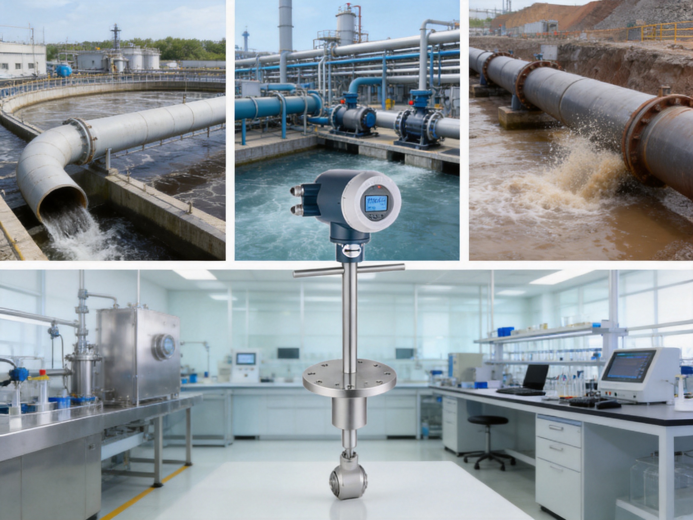
Water transmission mains are among the most natural applications for the VE15. Raw water, treated water, and many wastewater streams have adequate conductivity for electromagnetic measurement. The meter can be installed on large inlet lines, outlet lines, transmission mains, pumping headers, distribution networks, and outfalls.
In a municipal treatment plant, a DN1200 raw water pipeline may feed the treatment process continuously. An insertion meter can provide flow data for pump control, plant loading calculations, water balance, leak detection, and energy optimization. Because the installation may require less civil work than a full-bore meter, the plant can add measurement while limiting disruption to water supply.
Wastewater often contains suspended solids, organic matter, sludge, and variable liquid properties. The absence of moving parts is advantageous in this environment. The PTFE lining and suitable electrode material can support chemically demanding services, while IP68 or appropriate remote installation arrangements may be considered for chambers and exposed locations.
8.2 Industrial Water Systems
Industrial facilities frequently operate large cooling-water, process-water, firewater, and utility-water networks. Flow must be monitored not only at the main supply but also at major users such as furnaces, heat exchangers, reactors, compressors, and production areas.
In a closed-loop cooling system with DN800 to DN1600 lines, VE15 meters can be used to compare supply and return flow, identify distribution imbalance, verify minimum flow to critical equipment, and support maintenance planning. The stated velocity range of 0.5 to 8 m/s allows the same measurement concept to be considered for both moderate and higher-capacity services, subject to the actual hydraulic design.
Firewater systems require special attention to reliability, standby conditions, testing, and regulatory requirements. A flowmeter installed for monitoring or testing must not compromise the hydraulic performance or availability of the firewater system. The selection should therefore be reviewed with the responsible safety and fire-protection engineers.
8.3 Irrigation and Water Resources
Regional irrigation schemes often contain long, large-diameter pipelines serving multiple districts or agricultural zones. Master metering helps operators allocate water, compare delivered and expected volumes, identify losses, and improve pump scheduling.
Insertion technology is attractive for existing irrigation networks because it can reduce the amount of pipe reconstruction required. A series of meters on DN600 to DN1400 lines can provide measurement points at reservoirs, pumping stations, branch connections, and district boundaries. The result is a more detailed understanding of water movement through the network.
8.4 Food and Beverage Utilities
Food and beverage plants use large volumes of process water, cleaning water, cooling water, and other conductive utility liquids. The VE15 may be applied where the wetted materials are compatible with the medium and where the installation does not require a specialized sanitary full-bore design.
Applications can include utility transfer lines, water recovery systems, wastewater lines, and conductive liquid ingredients in large process systems. Hygiene, cleanability, material certification, temperature, cleaning chemicals, and local industry requirements should be evaluated before specifying the meter for a product-contact application.
8.5 Pulp and Paper
Pulp suspensions, white liquor, black liquor, mill effluent, and process water can present difficult measurement conditions. Suspended fibers and solids may make mechanical meters less attractive, while variable viscosity can complicate some other technologies. Electromagnetic measurement is often well suited when conductivity and materials compatibility are adequate.
The lining and electrode selection should reflect the chemical composition and temperature of the service. For abrasive or fiber-rich liquids, the installation should also consider the risk of buildup, cleaning requirements, and whether the probe location provides a representative velocity profile.
8.6 Mining and Metals
Mining and metals operations use large pipelines for process water, tailings, concentrates, return water, and slurries. The VE15 can support monitoring of conductive slurry and water flows in large lines, subject to an abrasion assessment.
Slurry applications require careful evaluation of solids concentration, particle size, density, velocity, settling behavior, chemical additives, and pipeline orientation. A higher velocity may help reduce settling, but it can increase wear. The meter should be specified with materials and installation practices suitable for the actual service rather than relying solely on general water-service data.
9. Comparison with Other Flowmeter Technologies
No flowmeter technology is ideal for every medium or pipeline. The main advantage of the VE15 is the combination of electromagnetic measurement and insertion construction. Comparing both aspects helps clarify where it offers the greatest value.
| Technology | Strengths | Potential Limitations Compared with VE15 |
|---|---|---|
| Full-bore electromagnetic meter | Direct measurement across the complete pipe cross-section and high accuracy in many applications | Higher purchase, handling, civil-work, and shutdown requirements on very large lines |
| Mechanical turbine meter | Useful for some clean-liquid applications and established totalizing duties | Moving parts can wear; solids, viscosity, and contamination may affect performance |
| Vortex meter | Effective for many gases, steam, and clean liquids | Requires a suitable velocity profile and is generally less suitable for sludge, pulp, and heavy solids |
| Ultrasonic meter | Can provide non-invasive or externally mounted measurement in selected conditions | Performance may depend strongly on acoustic properties, pipe condition, installation, and liquid quality |
| Rotameter | Simple local indication for smaller lines and lower flow ranges | Generally impractical for very large pipelines and remote digital networks |
| Coriolis meter | Provides direct mass flow and density-related information with high accuracy | Large sizes can be costly, heavy, and difficult to install; pressure loss may be higher |
| Insertion electromagnetic meter | Low obstruction, no moving parts, retrofit flexibility, and suitability for conductive dirty liquids | Requires careful insertion location, pipe-diameter configuration, grounding, and hydraulic installation |
Compared with a full-bore electromagnetic meter, the VE15 is most compelling when the pipeline is large, access is limited, budget is controlled, or the line cannot be taken out of service for a long period. A full-bore meter may remain preferable where the highest possible accuracy is required across a broad operating range, where the line is already being rebuilt, or where the meter forms part of a tightly controlled custody-transfer system.
Compared with turbine meters, the VE15 avoids mechanical rotation and is better suited to suspended solids and variable liquid properties. Compared with vortex meters, it is designed specifically for conductive liquids rather than primarily for gas, steam, or clean-liquid applications. Compared with ultrasonic meters, electromagnetic technology can be less dependent on acoustic transmission through the pipe wall, although it requires liquid conductivity and appropriate electrode contact.
These comparisons should be viewed as engineering guidance rather than absolute rules. The correct selection depends on the required accuracy, process medium, pipe size, installation geometry, maintenance philosophy, and total cost of ownership.
10. Converter, Outputs, and Control-System Integration
The microprocessor-based converter is the operational center of the VE15. It processes the electrode signal, applies the programmed pipe and calibration parameters, calculates flow, and transmits the result to the plant system. The converter may be supplied in an integrated or remote arrangement depending on the environment, accessibility, temperature, and installation requirements.
The standard 4–20 mA output is widely accepted for industrial flow transmission. It can represent instantaneous flow, velocity, or another configured process variable. The pulse output can be used for volume totalization, batch control, or connection to an external counter. Output scaling should be selected so that the normal operating range is represented with sufficient resolution while expected peak flow remains within the configured limit.
Modbus RS-485 communication can provide digital access to measured values, totalizers, status information, and configuration data, depending on the selected protocol implementation. HART can support communication over a conventional analog loop, while Profibus can integrate the meter into compatible automation architectures. These options make the instrument suitable for both simple local installations and larger plant-wide systems.
When integrating the meter into a SCADA, DCS, or PLC system, the project team should define measurement units, totalizer behavior, alarm limits, signal failure handling, communication addresses, update rates, and time synchronization requirements. A clear loop diagram and instrument data sheet can prevent commissioning delays.
11. Accuracy, Repeatability, and Application Expectations
The VE15 is specified with accuracy options of approximately ±1.0% or ±1.5% of rate, depending on the model, and repeatability options of approximately ±0.33% or ±0.5%. The selected performance class should match the purpose of the measurement. Operational monitoring, pump control, balancing, and leak detection may have different requirements from commercial allocation or regulatory reporting.
Accuracy is not determined by the converter alone. It is the result of the complete system, including the probe, calibration, pipe diameter, insertion depth, flow profile, liquid conductivity, grounding, and installation quality. A technically advanced meter installed at a poor location may not achieve its stated performance, while a carefully engineered installation can deliver stable and useful data over many years.
For large-diameter pipes, the ability to measure reliably at velocities from approximately 0.5 to 8 m/s provides useful flexibility. The actual operating range should be checked against minimum flow, maximum flow, pump curves, process turndown, and possible transient conditions. If the line frequently operates below the recommended velocity, the application may require a different meter size, a different measurement technology, or a revised measurement objective.
12. Commissioning and Maintenance
Commissioning begins with a review of the mechanical installation. The engineer should verify probe orientation, insertion depth, mounting tightness, valve position, pressure rating, cable entry, and enclosure condition. The pipe should be full, the liquid should be flowing within the expected range, and grounding should be checked before final signal evaluation.
Electrical commissioning includes confirming the power supply, output scaling, communication parameters, zero-flow behavior, totalizer settings, alarm configuration, and direction of flow. If the line can be isolated and brought to a confirmed no-flow condition, the zero point can be checked according to the operating instructions.
Routine maintenance is generally limited because the VE15 has no moving parts. Nevertheless, maintenance personnel should periodically inspect the enclosure, cable glands, mounting assembly, grounding connections, external corrosion, and signs of leakage. In difficult services, the probe and electrodes may require inspection for coating, deposits, chemical attack, or abrasion.
For buried or chamber installations, access planning is important. The design should provide a safe method for inspection and replacement. If the process cannot be interrupted, an isolation valve or suitable insertion assembly may be considered, subject to pressure and safety requirements.
13. Selecting the Correct Configuration
A successful VE15 specification should begin with the process data rather than the nominal pipe size alone. The following information is normally needed:
- Actual pipe internal diameter and pipe material
- Minimum, normal, and maximum flow rate
- Minimum, normal, and maximum flow velocity
- Operating and design pressure
- Operating and design temperature
- Liquid conductivity and chemical composition
- Suspended solids, pulp, sludge, or abrasive content
- Pipeline orientation and installation location
- Available upstream and downstream straight runs
- Required accuracy and repeatability
- Power supply and signal requirements
- Communication protocol and control-system architecture
- Environmental protection and hazardous-area classification
- Preferred body, lining, electrode, and cable materials
The electrode material should be selected according to the medium rather than treated as a standard accessory. 316L stainless steel is suitable for many ordinary water and industrial services, while Hastelloy may be more appropriate for aggressive chemical conditions. PTFE lining can support a wide range of chemical services, but the temperature and compatibility limits must be confirmed for the actual process.
The converter location should also be considered. A remote converter may be preferable where the probe is installed in a hot, flooded, vibrating, buried, or difficult-to-access area. An integrated arrangement may be convenient where the environment is controlled and local indication is important. The communication and enclosure options should be selected at the same time as the process connection to avoid later modifications.
14. Project Economics and Total Cost of Ownership
The economic benefit of the VE15 is not limited to the instrument price. Total project cost includes pipeline modification, civil work, lifting, transportation, installation labor, shutdown time, commissioning, cabling, control-system integration, and future maintenance. The insertion arrangement can reduce several of these cost elements, especially on large pipelines.
For a retrofit project, avoiding the removal of a large spool piece may reduce the duration of the shutdown. In a municipal network, this may help maintain water delivery. In an industrial plant, it may reduce production losses. In an irrigation network, it may limit service interruption during the operating season. The financial value of reduced disruption can be substantial even when the meter is used primarily for monitoring rather than direct sales measurement.
Lower pressure loss may also contribute to long-term energy savings. If a pumping system operates continuously, a small reduction in hydraulic resistance can accumulate into meaningful lifetime savings. The actual benefit depends on pump efficiency, operating hours, flow rate, electricity cost, and system design, so it should be calculated for each project.
Maintenance savings are another consideration. With no moving parts, the VE15 avoids routine replacement of bearings, impellers, and mechanical seals associated with some flowmeter types. This does not mean that the instrument is maintenance-free, but it can reduce the number of wear-related interventions in dirty or solids-bearing services.
15. Manufacturing and Supply Support for Industrial Projects
Industrial users often need more than a catalog instrument. They may require dimensional drawings, material certificates, calibration records, wiring diagrams, inspection plans, communication data, spare-parts information, and documentation formatted for an EPC or end-user approval process. A manufacturer with established project experience can support these needs more effectively than a supplier focused only on standard product shipment.
Jiangsu VNER Electronic Technology Co., Ltd. provides flow measurement products for liquid, gas, and slurry applications and supports EPC contractors, end users, and OEM partners. Its technical organization and multi-plant manufacturing base support project customization, product configuration, and engineering communication.
The company’s focus on in-house calibration, certified quality processes, traceability, and increasingly automated production supports consistency from design through final inspection. This is particularly important for a product such as the VE15, where mechanical assembly, electronics, software configuration, and calibration must work together as one measurement system.
More than 2,000 engineering projects in over 30 countries also indicate experience with international project environments. Different countries and industries may apply different flange standards, electrical practices, hazardous-area expectations, documentation formats, and acceptance procedures. Familiarity with DIN and ANSI/ASME connection standards, 24 V DC and 220 V AC power options, and common industrial communication protocols can simplify specification for international projects.
16. Practical Case Scenarios
16.1 Raw Water Transmission to a Treatment Plant
A municipal treatment plant receives raw water through a DN1200 transmission main. The existing pipeline is buried, and replacing a long section with a full-bore meter would require excavation, temporary bypass pumping, and a lengthy shutdown. An insertion electromagnetic meter can be installed through a prepared connection with significantly less civil work.
The measurement can be used to control pumping, compare inflow with treatment capacity, monitor daily and seasonal demand, identify unexpected losses, and support energy optimization. Because raw water is normally conductive and may contain suspended material, electromagnetic measurement is well matched to the service.
16.2 Cooling Water Distribution in a Process Plant
A steel, chemical, or petrochemical facility operates several closed-loop cooling circuits. The main headers range from DN800 to DN1600, and flow distribution to furnaces, heat exchangers, reactors, or other major consumers must be monitored continuously.
VE15 meters can be positioned on the main supply and return lines or on selected branches. The resulting data can reveal imbalance, declining pump performance, fouling, valve problems, or inadequate flow to critical equipment. The no-moving-parts design is beneficial for continuously circulating water, while digital communication can transmit values to the plant control system.
16.3 Wastewater Outfall Measurement
A DN1000 wastewater outfall requires continuous measurement for regulatory reporting and process control. The liquid contains suspended solids and may have variable chemical characteristics. A properly selected PTFE-lined electromagnetic insertion meter provides a practical measurement point without introducing a rotating mechanism into the discharge line.
For an outdoor or below-grade chamber, the enclosure and cable system should be selected for the expected water exposure. If the area contains hazardous gases or vapors, an appropriate Ex d configuration and compliant installation must be specified. The operator should also maintain access for inspection and verification.
16.4 Irrigation Master Metering
A regional irrigation network uses DN600 to DN1400 pipelines to distribute water to different districts. Historically, water allocation has been estimated from pump operation and valve position. Installing insertion electromagnetic meters at strategic master-metering points provides direct flow and total volume data.
The system can use these measurements to improve allocation, compare expected and delivered volume, identify leakage, and schedule pumps more efficiently. Since the meters can be added to existing pipelines with limited interruption, the network can be upgraded progressively rather than reconstructed all at once.
17. Limitations and Engineering Boundaries
The VE15 requires an electrically conductive liquid. It is therefore not the first choice for many hydrocarbons, oils, gases, steam, or other nonconductive media. Conductivity should be confirmed for the minimum and maximum process conditions, especially where dilution, chemical dosing, temperature variation, or batch changes may alter the liquid properties.
The meter also requires a full and hydraulically suitable pipe at the measurement point. A line that frequently drains, contains large air pockets, or operates with unstable free-surface conditions may require another measurement approach or a different installation location.
Insertion meters require more installation discipline than many users expect. The pipe diameter, insertion depth, orientation, and flow profile must be correct. If the line contains severe swirl or the available straight run is very short, the expected accuracy may not be achievable without additional hydraulic measures.
For abrasive slurries, the measurement principle may be suitable but the probe and lining must be assessed for wear. For high-temperature or aggressive chemical service, the selected materials and complete assembly must be reviewed. For hazardous areas, the Ex configuration and installation must comply with local regulations and project standards.
18. Recommended Specification and Procurement Checklist
Before placing an order, the purchaser should request a technical confirmation based on complete process data. The confirmation should identify the exact accuracy class, repeatability, pipe-size range, pressure rating, temperature limit, conductivity range, lining, electrode material, enclosure rating, hazardous-area option, power supply, outputs, communication protocol, process connection, cable interface, and mounting accessories.
The purchaser should also clarify whether the quoted accuracy applies to the complete insertion installation or to a specified calibration condition. The required straight runs and insertion orientation should be shown on the project drawing. If the meter is intended for an existing pressurized pipeline, the branch connection, isolation valve, insertion mechanism, and safe removal method should be included in the scope.
For EPC and utility projects, documentation requirements should be identified early. These may include general arrangement drawings, wiring diagrams, calibration certificates, material certificates, inspection and test plans, quality records, manuals, spare-parts lists, and certificates for communication or hazardous-area options. Early agreement reduces the chance of delays during approval and commissioning.
| Selection Area | Questions to Confirm |
|---|---|
| Process medium | Is the liquid conductive, and does its conductivity vary during operation? |
| Pipeline | What are the actual internal diameter, material, lining, orientation, and access conditions? |
| Hydraulics | What are the minimum, normal, and maximum velocities and flow rates? |
| Pressure | What are the normal pressure, design pressure, vacuum risk, and surge conditions? |
| Temperature | What are the normal, minimum, maximum, and cleaning temperatures? |
| Installation | Can suitable straight runs and a full-pipe condition be maintained? |
| Materials | Are PTFE, 316L stainless steel, or Hastelloy compatible with the medium? |
| Environment | Is IP65, IP67, IP68, or Ex d protection required? |
| Signals | Are 4–20 mA, pulse, Modbus, HART, or Profibus interfaces needed? |
| Service | Will the probe require inspection, isolation, removal, or periodic cleaning? |
19. Why the VE15 Is a Strong Large-Pipeline Solution
The VE15 combines the non-mechanical advantages of electromagnetic measurement with the installation economy of insertion technology. This combination makes it particularly useful for large-diameter pipelines where a full-bore meter would be expensive, disruptive, or physically difficult to install.
Its key advantages include a DN200 to DN4000 application range, minimal additional pressure loss, compatibility with conductive dirty liquids, no moving parts, flexible output and communication options, robust stainless steel construction, PTFE lining, multiple electrode materials, and protection options for demanding environments.
The instrument’s value is strengthened by the manufacturing and engineering capabilities of its supplier. A 23,000-square-meter, three-plant production base, a technical team of more than 150 people, in-house calibration, traceable quality processes, and experience across more than 2,000 projects provide a foundation for consistent industrial supply. The broad product range also allows the engineering team to compare electromagnetic measurement with other technologies when a project contains mixed liquid, gas, steam, slurry, or mass-flow requirements.
Compared with products that focus only on low-cost instrument delivery, an engineering-oriented approach can provide greater value over the life of the project. Accurate application selection, controlled manufacturing, documented calibration, reliable communications, and practical installation guidance all contribute to lower commissioning risk and better long-term performance.
The VE15 should not be selected solely because the pipeline is large. The liquid must be conductive, the pipe must remain full, and the installation must provide a representative flow profile. When these conditions are satisfied, the meter offers an economical and technically capable way to add dependable measurement to large water and industrial liquid networks.
20. Questions and Answers
Q1: What is the VE15 Insertion Electromagnetic Flowmeter?
The VE15 is an insertion-type electromagnetic flowmeter designed for large-diameter pipelines. It uses a probe installed through the pipe wall to measure the velocity of an electrically conductive liquid and calculates volumetric flow using the pipe diameter.
Q2: What pipe sizes can the VE15 measure?
The stated nominal pipe size range is DN200 to DN4000, or approximately 8 to 160 inches. The exact model and mounting arrangement should be confirmed according to the pipe and project requirements.
Q3: Which liquids can be measured?
The meter is intended for electrically conductive liquids, including raw water, treated water, wastewater, cooling water, process water, viscous liquids, pulp, sludge, and selected slurries. Conductivity and material compatibility must be verified before selection.
Q4: Can it measure liquids containing suspended solids?
Yes. Electromagnetic measurement is generally suitable for conductive liquids containing suspended solids, pulp, sludge, or certain slurries. Since the meter has no moving parts, it avoids many mechanical wear and blockage problems. Abrasive services still require a specific materials and wear assessment.
Q5: Does the VE15 create a significant pressure drop?
No. The insertion probe has no moving parts or full-bore mechanical obstruction, so the additional pressure loss is normally minimal when the installation is correctly designed.
Q6: Is a full-bore meter always more accurate?
A full-bore meter directly measures across the complete pipe cross-section and may be preferable for certain high-accuracy or custody-transfer applications. However, an insertion meter can provide stable and repeatable measurement when the probe position, pipe diameter, flow profile, grounding, and configuration are correct.
Q7: What accuracy is available?
Depending on the model, the specified accuracy is approximately ±1.0% or ±1.5% of rate. Repeatability is approximately ±0.33% or ±0.5%. The final performance depends strongly on installation and operating conditions.
Q8: What are the available outputs?
The product information specifies a 4–20 mA output and pulse output. Modbus RS-485, HART, and Profibus communication options are also available depending on the selected configuration.
Q9: Can the meter be used outdoors or in a wet chamber?
IP65, IP67, and IP68 versions are available depending on the model. The appropriate protection level, cable entry, converter location, and installation method must be selected for the actual environment.
Q10: Is an explosion-proof version available?
Ex d explosion-proof versions are available. The complete instrument and installation must satisfy the applicable hazardous-area classification, wiring, gland, grounding, and local certification requirements.
Q11: What materials are used for the wetted parts?
The standard configuration includes a PTFE lining and electrodes made from 316L stainless steel or Hastelloy. The electrode selection should reflect the chemistry, concentration, temperature, and cleaning conditions of the liquid.
Q12: What straight-run requirements apply?
The required straight runs depend on the upstream and downstream pipeline arrangement. Elbows, tees, reducers, valves, and pumps can distort the velocity profile. The installation should follow the manufacturer’s instructions and be reviewed by a qualified engineer when the available straight run is limited.
Q13: Can the VE15 be installed on an existing pipeline?
Yes. Retrofit installation is one of the main advantages of insertion technology. A suitable branch connection, fitting, valve, and mounting assembly are required. Pressurized installation must be engineered and carried out safely by qualified personnel.
Q14: What is the role of the manufacturer’s calibration process?
Calibration verifies the relationship between the flow condition and the instrument output. In-house calibration, documented quality processes, and traceability help support consistent measurement and provide useful records for commissioning and future maintenance.
Q15: What information should be supplied when requesting a quotation?
The purchaser should provide pipe size and internal diameter, liquid type and conductivity, minimum and maximum flow, pressure, temperature, pipe material, installation orientation, straight-run conditions, required accuracy, power supply, output signals, communication protocol, environmental conditions, and hazardous-area requirements.
21. Conclusion
Large-diameter flow measurement requires a balance between accuracy, installation practicality, process reliability, cost, and long-term serviceability. The VE15 Insertion Electromagnetic Flowmeter addresses these requirements with a compact probe-based design for DN200 to DN4000 pipelines.
Its electromagnetic operating principle is well suited to conductive water, wastewater, process liquids, pulp, sludge, and selected slurries. The lack of moving parts minimizes mechanical maintenance, while the limited internal obstruction helps reduce additional pressure loss. Flanged or plug-in mounting, flexible power options, analog and pulse outputs, digital communications, protective enclosures, and explosion-proof versions allow the product to be adapted to many industrial environments.
The strongest results will be achieved when the meter is treated as part of a complete measurement system. Correct pipe data, representative probe positioning, full-pipe operation, sound grounding, suitable materials, and proper commissioning are essential. Supported by an engineering-focused manufacturer with modern production facilities, in-house calibration, quality control, traceability, and broad international project experience, the VE15 provides a practical solution for improving visibility and control across large liquid pipeline networks.
References
1. Faraday, M. Experimental Researches in Electricity. Foundational work concerning electromagnetic induction.
2. International Electrotechnical Commission. Electromagnetic flowmeter principles, performance considerations, and industrial instrumentation practices.
3. International Organization for Standardization. Industrial process measurement and flowmeter installation guidance.
4. Manufacturer technical information for the VE15 Insertion Electromagnetic Flowmeter, including product specifications, materials, outputs, communication options, and installation notes.
5. Manufacturer quality and company information concerning calibration, traceability, manufacturing facilities, engineering resources, and international project experience.
6. General industrial pipeline engineering practice for flow-profile control, grounding, pressure containment, hazardous-area installation, and commissioning.
Product: VE15 Insertion Electromagnetic Flowmeter


We offer all our products and services at international standards.
Products
Contact Information
-

+86-18652789521
+86-18052582295
+86-0514-83633600 / 83633900 -

+86-0514-83633600 / 83633900
-

shawn@vnerflow.com
info@vnerflow.com -

No. 11 Xingye Road, Chenji Town Industrial Park, Yizheng, Yangzhou, China
