
 0
0
 EN
EN  English
 عربى
عربى Español
 русский
If you need any help, please feel free to contact us
Home / Author / Ren Xiaotong — Technical Sales Engineer for Gas Flow Meters / Electromagnetic Heat Meters for Accurate Thermal Energy Measurement in Heating and Cooling Systems
Electromagnetic Heat Meters for Accurate Thermal Energy Measurement in Heating and Cooling Systems
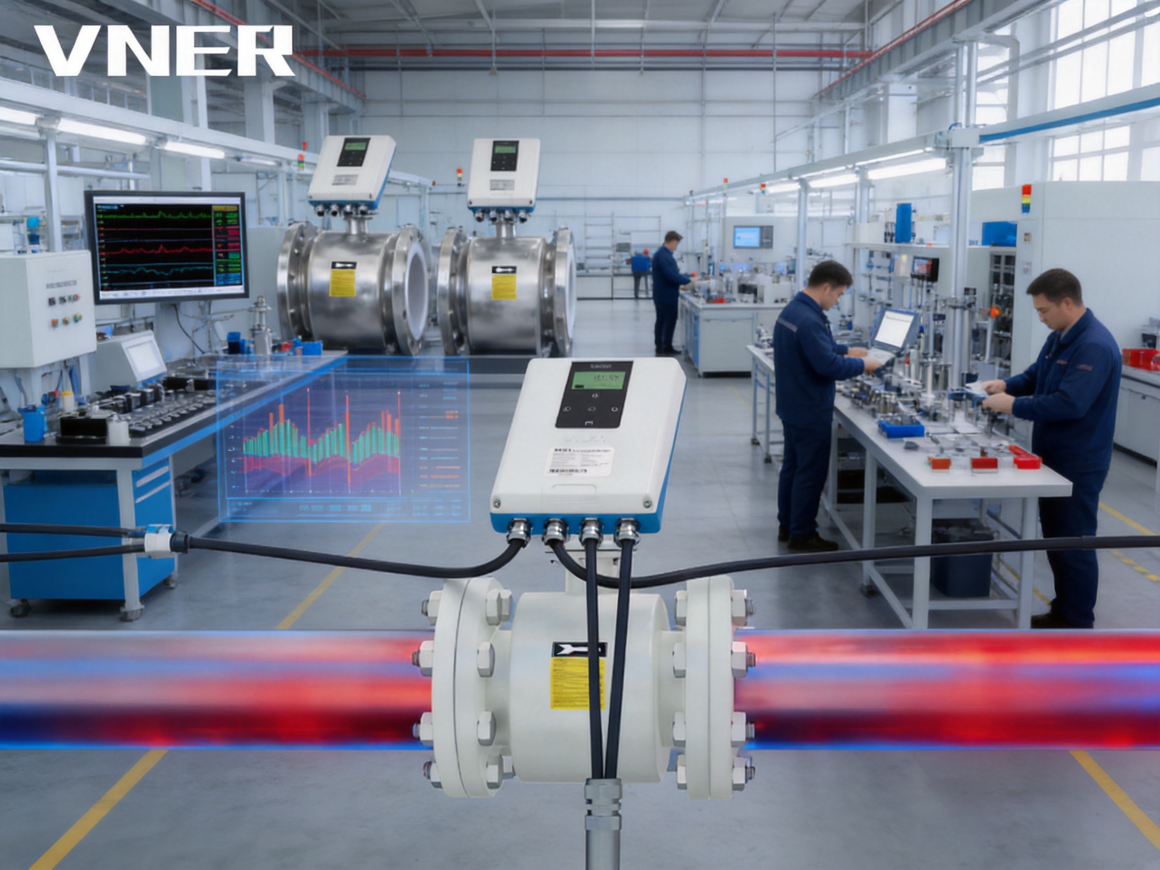
Thermal energy measurement has become increasingly important as building owners, district energy operators, industrial facilities and public utilities seek better control over heating and cooling costs. Accurate flow measurement is at the center of this process. Without reliable knowledge of how much hot or chilled water is moving through a system, temperature data alone cannot provide a dependable calculation of delivered or consumed energy.
The VE12 Electromagnetic Heat Meter is designed as a high-stability flow measurement solution for thermal energy metering. It measures the volumetric flow of electrically conductive liquids and supplies the flow data required by a complete heat-metering system. When installed with matched supply and return temperature sensors and connected to a dedicated heat calculator, it can support the calculation of thermal energy transferred through a heating or cooling circuit.
Unlike mechanical meters that depend on moving components, the VE12 uses electromagnetic induction. This design provides an unobstructed measuring bore, minimal pressure loss, bidirectional measurement and stable performance over a long operating life. It is suitable for hot water, chilled water, selected glycol mixtures and other conductive liquids used in building services, district energy and industrial process systems.
The meter is manufactured by Jiangsu Vner Electronic Technology Co., Ltd., a specialized Chinese industrial instrumentation company with experience in electromagnetic, Coriolis, vortex, swirl, turbine, thermal mass, ultrasonic and variable-area flow measurement technologies. The company combines in-house calibration, engineering-based sizing, certified quality processes and increasingly automated manufacturing to serve EPC contractors, industrial end users and OEM partners.
Why Thermal Energy Measurement Requires Reliable Flow Data
A thermal energy meter generally determines energy transfer by combining three fundamental measurements: the flow rate of the circulating medium, the temperature at the supply or inlet point and the temperature at the return or outlet point. The heat calculator uses these values, together with the physical properties of the fluid, to determine the energy delivered or removed.
In a heating application, hot water enters a building, process loop or heat exchanger at a higher temperature and returns at a lower temperature. The difference between the supply and return temperatures represents the heat released into the building or process. In a cooling application, chilled water absorbs heat and returns at a higher temperature. In both cases, the volume of fluid passing through the system is essential to the final energy calculation.
Small flow errors can become significant billing, balancing or efficiency errors when they are accumulated over thousands of operating hours. An unreliable flow signal may cause incorrect tenant billing, inaccurate performance evaluation, poor energy allocation or difficulty identifying heat exchanger fouling. For this reason, the flow sensor must maintain stable performance under changing flow, pressure and temperature conditions.
The VE12 is designed to provide this flow measurement function in a thermal energy metering arrangement. It does not replace the complete temperature measurement and heat calculation system. Instead, it provides the volumetric flow signal required by the calculator, allowing system designers to select suitable temperature sensors and energy calculation hardware for the relevant application and regulatory environment.
Electromagnetic Measuring Principle
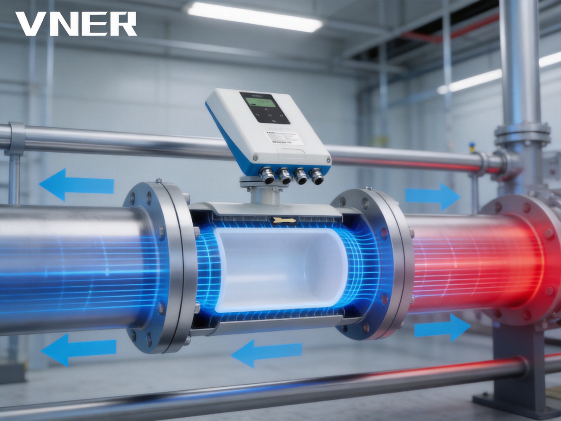
The VE12 operates according to Faraday’s law of electromagnetic induction. When an electrically conductive liquid moves through a magnetic field, a voltage is induced across the liquid. This voltage is proportional to the average velocity of the liquid in the measuring tube. The meter’s electrodes detect the induced signal, and the transmitter converts it into a flow-rate value.
Because the measurement is based on liquid velocity rather than mechanical displacement, the meter does not require an impeller, gear, turbine rotor or other moving element inside the flow path. The flow tube remains open and unobstructed. This is particularly useful in heating and cooling networks where stable operation, low maintenance and low pressure loss are more important than mechanical simplicity alone.
The liquid must have sufficient electrical conductivity for electromagnetic measurement. Hot water and chilled water are normally well suited. Many water-based glycol mixtures can also be measured, although the actual conductivity should be checked during application selection. Non-conductive liquids, gases and dry products are not suitable for this measuring principle.
The electromagnetic principle is largely independent of fluid density, viscosity and pressure. This gives the VE12 an important practical advantage in thermal systems where operating conditions may vary. Changes in water temperature, fluid composition or pressure do not affect the measurement in the same manner as they may affect certain mechanical or differential-pressure devices. Correct installation, grounding, full-pipe conditions and appropriate calibration remain essential for dependable results.
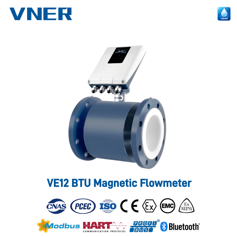
VE12 Electromagnetic Heat Meter (BTU)
Product Design and Main Technical Characteristics
The VE12 is an electromagnetic flowmeter configured for use as the flow sensor in heat-metering systems. It is available across a broad nominal diameter range from DN6 to DN2000, approximately equivalent to 1/8 inch through 80 inches. This range allows the same general measurement technology to be applied to small building branches, larger plant headers and district energy pipelines.
The stated accuracy is ±0.5 percent of rate, while repeatability is typically 0.16 percent of rate. Accuracy describes how closely the indicated measurement corresponds to the actual flow under specified conditions. Repeatability describes how consistently the instrument produces the same result when the same flow condition is repeated. Both characteristics matter in energy management because thermal consumption is usually integrated over long periods.
The recommended flow velocity range is 0.3 to 10 meters per second. System designers should select the meter size so that normal operating flow remains within a suitable portion of this range. Oversizing may result in low velocity and reduced signal strength, while undersizing may increase pressure loss or push the meter toward the upper limit of its operating range. Engineering-based sizing is therefore more reliable than selecting a nominal diameter only from the connected pipe size.
The flowmeter supports forward and reverse flow measurement. Bidirectional capability is valuable in systems where circulation direction may change during commissioning, seasonal operation, flushing or special operating modes. It also provides useful diagnostic information when unexpected reverse flow occurs in a heating or cooling loop.
Flanged process connections are available according to DIN and ANSI/ASME standards. Depending on the model and configuration, nominal pressure ratings range from 0.6 to 4 MPa, with ANSI 150 and ANSI 600 options available for applicable designs. The selected pressure class must match the pipeline design pressure, temperature, flange standard and installation environment.
Available lining materials include PTFE, FEP and PFA. These materials provide electrical insulation between the process liquid and the meter body while also supporting chemical and temperature resistance. Electrode options include 316L stainless steel, Hastelloy and titanium. The selection should take into account fluid chemistry, conductivity, temperature, concentration and the possibility of corrosion or abrasion.
The meter body can be manufactured from 304 or 316 stainless steel. Stainless construction supports use in utility plants, building mechanical rooms, industrial process areas and other installations where durability and resistance to environmental conditions are important.
Electrical and Communication Functions
The VE12 can be supplied with 24 V DC or 220 V AC power, depending on the selected version and the requirements of the installation. Its output functions include a 4–20 mA signal, pulse or totalizer output and an optional Bluetooth interface. Modbus RS-485 communication is available for digital integration with building management systems, programmable controllers, supervisory systems and energy management platforms.
The 4–20 mA output is commonly used for transmitting instantaneous flow rate over an industrial signal loop. A pulse or totalizer output can be used to represent accumulated volume or support external energy calculation equipment. Digital communication can provide access to measurement values, totalized flow, configuration parameters and diagnostic information, depending on the final instrument configuration.
Electrical connections may use M20 × 1.5 or 1/2-inch-14 NPT cable entries. Protection ratings include IP65, IP67 and IP68 according to the version. The appropriate enclosure and cable arrangement should be selected according to whether the meter is installed indoors, outdoors, in a wet plant room, in a chamber or in a location subject to temporary or continuous immersion.
The meter may be supplied with ISO, CE or ATEX-related certifications according to model and region. Certification requirements should be confirmed during quotation and before installation, especially for projects involving hazardous areas, regulated billing, export compliance or specific local standards.
Advantages Compared with Conventional Flow Measurement Technologies
No Moving Parts in the Process Flow
A major advantage of the VE12 is the absence of moving parts in the measuring tube. Mechanical turbine and positive-displacement meters may contain rotors, bearings, gears or other components that experience wear. Suspended solids, deposits and changes in lubrication or mechanical friction can affect their performance over time.
The electromagnetic meter measures the liquid without placing a rotating element in the flow path. This can reduce mechanical wear and simplify long-term maintenance. It also avoids the pressure loss associated with some internal mechanical assemblies. For building and district heating networks, lower pressure loss can help reduce unnecessary pump energy consumption, particularly when many meters are installed across a large system.
Stable Measurement for Water-Based Thermal Systems
Heating and cooling systems are rarely operated at one fixed condition throughout the year. Flow can change as valves open and close, pumps modulate, occupancy varies and outdoor conditions change. The temperature of the circulating liquid also changes between operating modes.
Because electromagnetic measurement is based on liquid velocity and is largely independent of density and viscosity, the VE12 can provide stable volumetric flow measurement under these changing conditions. This is a practical benefit over measurement methods whose performance may be more strongly influenced by fluid properties or mechanical behavior.
Low Pressure Loss and Full-Bore Construction
The unobstructed bore allows the liquid to pass through the meter with negligible pressure loss compared with many restriction-based devices. This characteristic is valuable in chilled-water and hot-water loops where pump head is carefully managed. Lower resistance can contribute to more efficient system operation and may reduce the need for additional pumping capacity.
The full-bore construction can also be beneficial in water circuits where deposits or suspended particles may occasionally be present. Although good filtration, water treatment and commissioning practices remain important, there is no small mechanical passage that must be protected from every particle in the same way as certain precision mechanical meters.
Bidirectional Flow Measurement
Many conventional flow applications are designed around one expected direction. In real thermal systems, however, reverse flow may occur during system balancing, temporary bypass operation, pump switching or seasonal changes. The VE12 can measure both forward and reverse flow, helping operators identify actual circulation behavior and improving the flexibility of the installation.
Broad Size and Material Selection
The DN6 to DN2000 diameter range supports projects from small branch circuits to large distribution pipelines. A selection of lining, electrode and body materials allows the meter to be adapted to clean water, treated water and certain water-based process fluids.
This material flexibility is especially useful for industrial energy management. A facility may use ordinary hot water in one loop, chilled water in another and a glycol mixture in a third. The same electromagnetic technology can be considered for each circuit, provided conductivity, temperature, pressure and chemical compatibility are confirmed.
Digital Integration and Practical Outputs
Modern thermal energy systems require more than a local display. Operators increasingly need to transfer flow data to building automation systems, central energy dashboards and remote maintenance platforms. The VE12 supports common industrial interfaces, including 4–20 mA, pulse or totalizer signals and Modbus RS-485.
The optional Bluetooth interface can support convenient local access where appropriate. Digital connectivity helps reduce manual reading, improves data availability and allows energy information to be compared across buildings, tenants, production lines or plant areas.
Application in District Heating
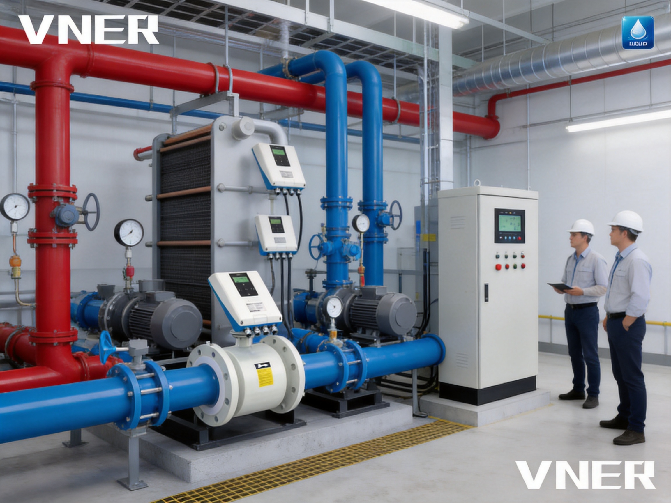
District heating substations transfer thermal energy from a central network to a building or local distribution system. A typical substation includes a supply line, a return line, heat exchangers, control valves, pumps and temperature measurement points. The VE12 can be installed in the relevant hot-water line to measure the flow entering or leaving the energy transfer system.
When paired with supply and return temperature sensors, the flowmeter supports calculation of delivered thermal energy. This can be used for billing, contractual settlement, system balancing or operational monitoring. Reliable data can help the energy supplier compare the energy sent into a substation with the energy returned, while building operators can review consumption against occupancy and weather conditions.
District heating networks often include many substations and branches. A consistent meter platform can simplify procurement, training, spare-parts planning and data integration. The broad diameter range allows the technology to be applied at different points in the network, although each meter must still be sized and configured for its specific duty.
In a district heating environment, installation quality is particularly important. The pipe should remain full during measurement, the flow profile should be sufficiently developed, and the meter should be properly grounded. Temperature sensors must be installed at representative supply and return locations, and the heat calculator must be configured with the correct fluid and energy units.
Application in District Cooling and Building HVAC
District cooling systems circulate chilled water from a central plant to buildings or tenant substations. As the water absorbs heat, its temperature rises before it returns to the cooling plant. The VE12 measures the circulating volume, while temperature sensors measure the difference required to determine cooling energy.
In commercial buildings, hospitals, hotels, campuses and residential developments, thermal energy measurement may be required at the building entrance, floor level, tenant boundary or individual air-handling system. The meter can support energy allocation between different areas, allowing facility managers to identify abnormal consumption and improve cost transparency.
Heating, ventilation and air-conditioning systems often operate with variable-speed pumps and modulating control valves. Flow rates can therefore change considerably over the day. A flow sensor with good repeatability and digital communication can help the control system understand actual circulation rather than relying only on valve position or pump speed.
By combining flow data with supply and return temperatures, building operators can evaluate whether a cooling coil, air-handling unit or fan-coil loop is delivering the expected thermal performance. Unexpectedly high flow with a small temperature difference may indicate poor heat transfer, control problems, incorrect balancing or bypass flow.
For tenant billing and cost allocation, the complete metering system should be selected according to applicable local requirements. The VE12 provides the flow measurement component, while temperature sensor accuracy, calculator performance, installation conditions and verification procedures also influence the final energy measurement.
Industrial Energy Management and Heat Exchanger Monitoring
Industrial plants use heating and cooling water in heat exchangers, process heaters, reactors, dryers, compressors, furnaces, cooling skids and utility networks. Energy may be transferred between a central utility system and many individual process units. Measuring the flow through each important circuit can reveal how much energy is being consumed and whether the equipment is operating efficiently.
For example, a heat exchanger may be designed to transfer a specific amount of energy at a defined flow rate and temperature difference. If the VE12 detects a gradual decline in flow or if the calculated energy transfer falls below the expected value, maintenance personnel can investigate valve operation, pump performance, fouling, scaling or air accumulation.
Glycol-water mixtures are commonly used where freeze protection is required. These mixtures can often be measured by electromagnetic technology when their electrical conductivity is sufficient. The actual fluid composition and temperature should be confirmed before selecting the lining and electrode materials.
Industrial facilities also benefit from the meter’s bidirectional capability. Temporary process changes, alternate pumping arrangements and bypass lines can create flow reversals that are difficult to identify using a unidirectional measurement system. Capturing reverse flow can improve troubleshooting and help engineers verify the actual operating state of a process loop.
Manufacturing Strengths and Engineering Capability
The performance of an industrial flowmeter depends not only on its measuring principle but also on manufacturing discipline. Dimensional accuracy, electrode positioning, lining quality, welding, assembly, electronic testing and calibration all influence the final result. Jiangsu Vner Electronic Technology Co., Ltd. has developed its manufacturing and engineering capabilities around a broad industrial flow measurement portfolio.
The company operates modern facilities covering approximately 23,000 square meters across three plants. Its technical team includes more than 150 personnel, supporting product development, application engineering, production, calibration, quality management and customer service. This scale provides a foundation for handling both standard instruments and customized project requirements.
In-House Calibration
In-house calibration is an important part of the production process. Flowmeters must be tested against controlled reference conditions so that the relationship between actual flow and indicated flow can be verified. Calibration data also supports traceability, product consistency and the preparation of project documentation.
For customers, an organized calibration capability can improve confidence that instruments have been checked before shipment. It also enables the manufacturer to investigate performance questions, support application-specific testing and maintain a closer relationship between production and measurement verification.
Calibration should not be viewed as a substitute for correct field installation. A meter can be accurately calibrated at the factory yet perform poorly if the pipe is not full, grounding is incomplete, the flow profile is disturbed or the selected size is unsuitable. The strongest results come from combining controlled factory calibration with sound installation engineering.
Certified Quality Processes
Certified quality processes help organize manufacturing around repeatable procedures rather than individual judgment. For a flowmeter, this can include incoming material checks, body and lining inspections, electronic assembly verification, dimensional control, pressure testing, signal testing, final calibration and documentation review.
Such processes are especially important when meters are supplied for large EPC projects or distributed across multiple countries. Consistent inspection and recordkeeping help customers manage project acceptance, spare parts and future maintenance. The available ISO, CE and model- or region-dependent ATEX certifications can further support market and application requirements when the correct version is selected.
Automated and Controlled Production
Increasingly automated manufacturing can improve repeatability in assembly and reduce variation between units. Automation does not eliminate the need for experienced engineers and technicians; instead, it supports them by making recurring operations more consistent and easier to monitor.
Controlled manufacturing is valuable for electromagnetic meters because sensor geometry, electrode installation and electronic configuration must work together. Consistency in these areas contributes to reliable zero stability, signal processing and calibration performance.
Engineering-Based Sizing and Selection
Flowmeter selection is an engineering task, not simply a product catalog choice. The appropriate diameter, lining, electrodes, pressure class, power supply, output configuration, enclosure rating and certification depend on the application.
VNER supports engineering-driven sizing and selection for liquid, gas and slurry applications. For the VE12, application review should consider normal, minimum and maximum flow; fluid conductivity; operating temperature; pressure; pipe material; installation position; flow direction; required communication; environmental conditions and the intended energy calculation method.
This approach can help avoid common problems such as excessive meter size, insufficient velocity, unsuitable electrode material, incompatible lining, incorrect pressure rating or missing communication functions. It also supports OEM and EPC customers that need a repeatable technical basis for equipment specifications.
Installation Considerations for Reliable Measurement
Maintaining a Full Measuring Tube
Electromagnetic flowmeters should normally operate with the measuring tube completely filled. If the pipe is only partially full, the meter may interpret the liquid level incorrectly because the measured signal no longer represents the full cross-sectional area. Installation should therefore avoid locations where the pipe can drain, form a free surface or experience frequent air accumulation.
Suitable locations may include vertical upward-flow sections, lower sections of a piping system or areas downstream of a pump where the pipe remains full. The final arrangement depends on the system design, pressure conditions and maintenance requirements.
Flow Profile and Straight Runs
Valves, elbows, reducers, pumps and tees can disturb the flow profile. The meter should be installed with sufficient straight pipe or according to the manufacturer’s recommended installation requirements. The necessary length depends on the upstream and downstream arrangement and should be confirmed for the specific model.
Correct alignment is also important. The meter should be centered between flanges without placing excessive mechanical stress on the body. Gaskets should not extend into the measuring bore, because an obstruction can affect the flow profile and reduce measurement quality.
Grounding and Electrical Noise
Electromagnetic meters measure a small induced voltage, so grounding and electrical installation must be handled carefully. Proper grounding provides a stable reference and helps reduce the influence of electrical interference. The grounding method depends on the pipe material, lining, process connection and local electrical requirements.
Signal cables should be routed in a manner that limits exposure to high-power cables, variable-frequency drives and other sources of electromagnetic interference. Cable glands must be tightened correctly to preserve enclosure protection, especially in outdoor or wet environments.
Temperature Sensor Placement
For thermal energy measurement, supply and return temperature sensors should represent the actual temperature of the fluid entering and leaving the energy transfer system. Poor sensor placement can produce an inaccurate temperature difference even when the flowmeter is operating correctly.
The sensors should be installed where mixing is adequate and where heat loss or external heating is minimized. The supply and return sensors should be matched and connected to a compatible heat calculator. The calculator must be configured for the correct energy units, fluid properties and sensor input characteristics.
Commissioning and Verification
Commissioning should include inspection of the meter orientation, flange connections, wiring, power supply, grounding, communication settings and flow direction. The line should be flushed before operation when construction debris or welding residue may be present.
Operators should compare the indicated flow with expected pump, valve and process conditions. Totalized volume can be reviewed over a known operating period, and communication values should be checked against the local display or commissioning tools. Any unusual zero reading, fluctuating signal or unexplained reverse flow should be investigated before the meter is placed into service for billing or formal energy reporting.
Material Selection for Different Thermal Fluids
The lining forms the internal insulating and protective surface of the flow tube. PTFE, FEP and PFA are available options, with the final choice depending on temperature, fluid chemistry and mechanical requirements. Hot water and chilled water are generally compatible with common electromagnetic flowmeter linings, but the full operating envelope should always be reviewed.
Electrode selection is equally important. 316L stainless steel is widely used for ordinary water services and many general industrial applications. Hastelloy may be selected where greater resistance to specific corrosive conditions is required. Titanium can be appropriate for certain water chemistries and demanding environments.
Stainless steel 304 or 316 bodies provide a durable structural enclosure. In a plant room, the body material must be considered together with humidity, chemical exposure, outdoor installation, insulation practices and mechanical loading from the pipeline.
Material compatibility should be confirmed using actual process information rather than a general fluid name. “Glycol mixture,” for example, may refer to different glycol types, concentrations, inhibitors and treatment chemicals. These details can affect conductivity, corrosion behavior and temperature performance.
Data Integration for Energy Management
The value of a thermal energy meter increases when its data can be integrated into a broader management system. A local display supports commissioning and routine checks, but a building management system can compare multiple circuits, identify trends and generate automated alarms.
Modbus RS-485 communication allows the VE12 to exchange data with compatible control or monitoring equipment. Depending on the final configuration, users may access flow rate, accumulated flow, status information and other operating parameters. The 4–20 mA output can be connected to an analog input, while pulse output can be used for volume accumulation or external calculation.
Data from several meters can be combined to create a plant-level energy balance. A facility manager may compare energy entering a building with energy allocated to individual tenants. An industrial engineer may compare the heat supplied to several production lines. A district energy operator may compare substation demand across different service areas.
Historical data also supports preventive maintenance. A declining temperature difference, increasing flow requirement or changing consumption pattern may indicate control valve problems, fouling, insulation deterioration or changes in operating schedules. The flowmeter is therefore not only a billing instrument; it can also be part of a wider efficiency and asset-management strategy.
Quality, Reliability and Lifecycle Value
Lifecycle value includes more than the initial purchase price. It also includes installation cost, pressure loss, maintenance frequency, calibration requirements, spare parts, downtime and the quality of data delivered to the energy management system.
The VE12’s non-mechanical construction can help reduce wear-related maintenance. Its broad material and size options can simplify specification across different circuits. Its communication choices support integration with modern automation systems. Factory calibration and controlled production provide a foundation for consistent performance from one instrument to the next.
Long service life is also supported by the absence of moving parts and the use of robust body and lining materials. Nevertheless, long-term reliability depends on proper application selection. A meter exposed to a fluid outside its conductivity range, temperature rating or pressure class cannot be expected to perform correctly simply because the electromagnetic principle is generally durable.
Routine maintenance may include checking connections, inspecting the installation environment, reviewing diagnostic information and confirming that the pipe remains full during operation. In systems used for commercial settlement or regulated billing, periodic verification should follow applicable local requirements.
Comparison with Common Alternatives
| Measurement Technology | Typical Strength | Considerations in Thermal Energy Systems |
| Electromagnetic flowmeter | No moving parts, low pressure loss, bidirectional measurement and good suitability for conductive water-based fluids | Requires adequate liquid conductivity and a full pipe |
| Mechanical turbine meter | Can be compact and familiar for clean-liquid applications | Moving parts may wear; pressure loss and sensitivity to fluid conditions may increase over time |
| Positive-displacement meter | Can provide direct volumetric measurement at lower flow rates | Moving chambers or gears may require maintenance and may be sensitive to contamination or pressure loss |
| Ultrasonic flowmeter | Some designs can be installed externally without cutting the pipe | Performance may depend on pipe condition, acoustic properties, installation quality and fluid conditions |
| Vortex flowmeter | Useful for certain liquid, gas and steam applications | Requires suitable flow conditions and is generally less appropriate for low-velocity water circuits or highly variable flow |
| Differential-pressure meter | Widely understood and compatible with many process systems | Creates a permanent pressure drop and requires pressure measurement and impulse-line management |
The best technology depends on the application. The VE12 is not intended to measure every fluid or replace every type of flowmeter. Its strongest advantages appear in conductive liquid services where low pressure loss, stable volumetric measurement, low mechanical maintenance and digital integration are priorities.
Selection Guide for Project Engineers
Before ordering a VE12, project engineers should prepare a complete set of operating data. The most important information includes the fluid name, conductivity, concentration if applicable, minimum and maximum flow, normal flow, operating temperature, design pressure, pipe diameter, connection standard and installation environment.
The required output and communication functions should also be specified. A basic installation may require only a local display and pulse output. A large building or industrial plant may require 4–20 mA, Modbus RS-485, totalization, remote data collection and a high enclosure protection rating.
Certification and compliance requirements should be reviewed at the beginning of the project. If the meter is installed in a hazardous location, the applicable ATEX or regional certification must match the complete installation. If the meter is used for commercial billing, local metering and verification requirements may apply to the entire heat-metering system.
Temperature sensors and the heat calculator should be considered at the same time as the flowmeter. A flow sensor cannot independently determine thermal energy. The final system requires compatible temperature measurement, correct sensor placement, suitable calculation software or hardware and a documented commissioning procedure.
Role of the Manufacturer in Project Success
Industrial flow measurement projects often involve more than supplying a standard instrument. The manufacturer may need to review process data, confirm materials, recommend a meter size, select outputs, prepare drawings, provide calibration documents and support installation questions.
Jiangsu Vner Electronic Technology Co., Ltd. has focused on industrial flow measurement since 2011. Its product portfolio covers electromagnetic and other flow technologies for liquid, gas and slurry services. This broad experience can be useful when an engineering project includes several different measurement duties and requires a consistent technical partner.
The company reports more than 2,000 engineering projects in over 30 countries and supports EPC contractors, end users and OEM partners in oil and gas, petrochemical, polysilicon, power, water and wastewater and related industrial sectors. Experience across these sectors helps connect instrument design with practical process conditions rather than treating each meter as an isolated catalog item.
Its facilities, technical team, calibration resources and automated production initiatives support a manufacturing model focused on product consistency, traceability and long-term reliability. For customers, this can make it easier to manage repeat orders, project documentation, quality inspections and technical communication across multiple installations.
Q&A: Frequently Asked Questions
What does the VE12 measure?
The VE12 measures the volumetric flow rate of electrically conductive liquids. In a thermal energy metering system, it provides the flow measurement used together with supply and return temperature data to calculate heating or cooling energy.
Can the VE12 measure hot water and chilled water?
Yes. Hot water and chilled water are typical applications, provided the operating temperature, pressure, conductivity and material compatibility fall within the selected model’s specifications.
Is the VE12 a complete heat calculator?
The VE12 is the flow sensor component of a heat-metering solution. A complete system normally includes the electromagnetic flowmeter, paired temperature sensors and a dedicated heat calculator or compatible energy management system.
Can glycol mixtures be measured?
Many glycol-water mixtures can be measured if they have adequate electrical conductivity. The exact glycol type, concentration, temperature and chemical composition should be reviewed before selection.
Does the meter have moving parts?
No. The electromagnetic measuring tube has no turbine, impeller or other moving measuring component. This helps reduce mechanical wear and supports low-maintenance operation.
What is the accuracy of the VE12?
The stated accuracy is ±0.5 percent of rate, with typical repeatability of 0.16 percent of rate. Actual performance depends on the selected model, installation conditions, calibration and application range.
Can it measure reverse flow?
Yes. The VE12 supports bidirectional forward and reverse flow measurement. This can be useful in systems where circulation direction changes or where reverse flow must be identified for troubleshooting.
What sizes are available?
Nominal diameters range from DN6 to DN2000, approximately 1/8 inch to 80 inches. The correct size should be selected from minimum, normal and maximum flow conditions rather than pipe diameter alone.
What outputs are available?
Available functions include 4–20 mA, pulse or totalizer output and an optional Bluetooth interface. Modbus RS-485 digital communication is also available according to the selected configuration.
What lining materials can be selected?
Available lining materials include PTFE, FEP and PFA. The selection depends on temperature, fluid chemistry and process requirements.
Which electrode materials are available?
Electrode options include 316L stainless steel, Hastelloy and titanium. The most suitable option depends on the conductivity and chemical characteristics of the measured liquid.
What should be considered during installation?
The pipe should remain full, the meter should be installed with an appropriate flow profile, the electrodes and lining should be compatible with the fluid, and grounding and cable installation should be completed correctly. Supply and return temperature sensors must also be positioned properly for thermal energy calculation.
Is the VE12 suitable for commercial energy allocation?
It can support building-level, tenant-level and district energy measurement when incorporated into a complete thermal energy metering system. Any legal metering, billing or verification requirements must be checked for the applicable region.
How does the meter reduce maintenance compared with mechanical meters?
Because it has no moving parts in the process flow, it avoids many mechanical wear mechanisms associated with rotors, gears and bearings. Routine inspection and verification are still recommended, particularly in critical or billing applications.
Can the meter be used outdoors or in wet areas?
Versions are available with IP65, IP67 or IP68 protection ratings, depending on the model. The selected protection level, cable entries and installation method must match the actual environment.
What support can an industrial manufacturer provide?
Support may include process review, meter sizing, material selection, output configuration, calibration documentation, installation guidance and project-specific technical communication. Engineering-based selection is especially valuable for large or customized thermal energy systems.
Conclusion
The VE12 Electromagnetic Heat Meter provides a practical flow measurement foundation for heating, cooling and industrial thermal energy systems. Its Faraday-law operating principle is well suited to conductive liquids such as hot water, chilled water and many glycol mixtures. The absence of moving parts, unobstructed bore, low pressure loss, bidirectional capability and broad material and size selection give it strong advantages in demanding utility and process applications.
When combined with accurate supply and return temperature sensors and a dedicated heat calculator, the VE12 can support energy billing, cost allocation, system balancing, efficiency monitoring and heat exchanger performance analysis. Its 4–20 mA, pulse, totalizer, Bluetooth and Modbus RS-485 options also allow it to participate in modern building automation and industrial energy management systems.
The product’s value is reinforced by the manufacturer’s broader engineering and production capabilities. Modern facilities, a substantial technical team, in-house calibration, certified quality processes, traceability and increasingly automated manufacturing provide a structured basis for consistent instrument production. Experience with multiple flow technologies and international engineering projects further supports application-specific selection.
For the best results, users should treat the meter as part of a complete measurement system. Correct sizing, fluid compatibility, full-pipe installation, grounding, temperature sensor placement, heat calculator configuration and commissioning all contribute to final accuracy. With these requirements properly addressed, the VE12 can deliver reliable flow data for long-term thermal energy management across district heating, district cooling, HVAC and industrial utility networks.
References
1. Faraday, M. Principles of electromagnetic induction and their application to electrical measurement.
2. International technical guidance on electromagnetic flow measurement for conductive liquids.
3. General engineering practices for district heating and district cooling thermal energy metering.
4. Industrial instrumentation principles for flowmeter sizing, grounding, calibration and commissioning.
5. Technical specifications and application information supplied for the VE12 Electromagnetic Heat Meter.
6. Manufacturer information concerning industrial flow measurement, calibration, quality management and manufacturing capabilities.
Product: VE12 Electromagnetic Heat Meter (BTU)


We offer all our products and services at international standards.
Products
Contact Information
-

+86-18652789521
+86-18052582295
+86-0514-83633600 / 83633900 -

+86-0514-83633600 / 83633900
-

shawn@vnerflow.com
info@vnerflow.com -

No. 11 Xingye Road, Chenji Town Industrial Park, Yizheng, Yangzhou, China
