
 0
0
 EN
EN  English
 عربى
عربى Español
 русский
If you need any help, please feel free to contact us
Home / Author / Ren Xiaotong — Technical Sales Engineer for Gas Flow Meters / Hygienic Small-Bore Electromagnetic Flowmeters for Precise Industrial Liquid Measurement
Hygienic Small-Bore Electromagnetic Flowmeters for Precise Industrial Liquid Measurement
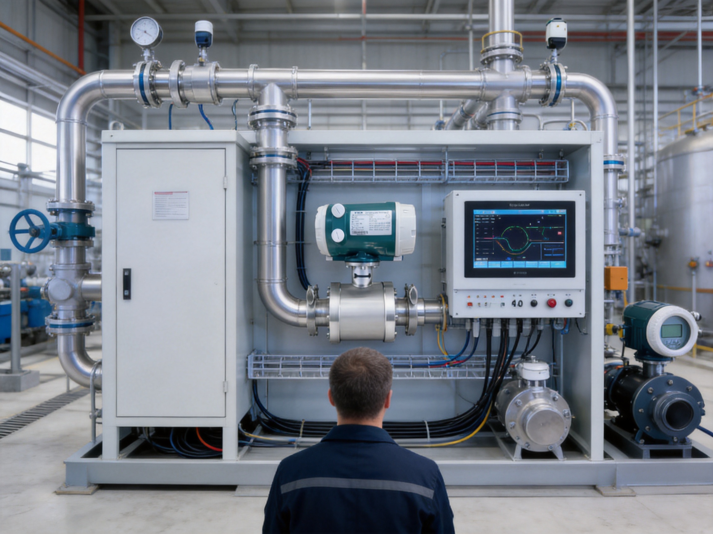
Accurate liquid-flow measurement is essential in modern process industries. Food and beverage plants, chemical facilities, water-treatment systems, equipment manufacturers and compact process skids all require dependable instruments that can measure flow consistently while fitting into restricted installation spaces. In hygienic and small-bore applications, the flowmeter must do more than provide a numerical reading. It must also support cleanable process connections, resist corrosion, minimize pressure loss, integrate with control systems and remain stable when operating conditions change.
The VE13 Hygienic Electromagnetic Flowmeter is designed for these requirements. It is a compact electromagnetic flowmeter for electrically conductive liquids and selected slurries. Its full-bore measuring tube has no moving parts or intrusive obstructions, while its stainless-steel construction and threaded or Tri-Clamp connections make it suitable for hygienic lines, compact equipment and process skids. Depending on the selected configuration, the instrument can be supplied with FEP or PFA lining, stainless-steel or special-alloy electrodes, 4-20 mA and pulse outputs, Modbus RS-485 or HART communication, and explosion-proof options.
Rather than relying on mechanical components that can wear, clog or create additional resistance, the VE13 uses Faraday’s law of electromagnetic induction. This principle enables the meter to measure volumetric flow without placing a turbine, impeller or other moving element in the process stream. The result is a robust design with low maintenance requirements and a broad range of industrial applications.
Why Small-Bore Hygienic Flow Measurement Requires a Specialized Design
Small process lines create several measurement challenges. A flowmeter installed on a compact line may have limited straight-run space, restricted access for maintenance and a higher risk of process contamination if the internal design is difficult to clean. In hygienic applications, the meter may also be exposed to frequent washing cycles, cleaning chemicals, temperature changes and viscous or particulate-bearing liquids.
A conventional mechanical flowmeter may introduce moving parts into the liquid. These parts can be affected by suspended solids, viscosity changes, deposits or wear. They may also produce pressure loss and require periodic servicing. In addition, mechanical measuring elements can be difficult to clean thoroughly when the process demands sanitary operation.
The VE13 addresses these issues with an unobstructed measuring bore. Because the meter has no internal rotor, paddle, bearing or impeller, the liquid flows through a continuous passage. This configuration helps reduce the risk of clogging and avoids the additional pressure loss associated with many intrusive measuring technologies. It is particularly useful where the process must maintain stable pumping conditions or where the available pump capacity is limited.
The hygienic design is also supported by stainless-steel body options and sanitary Tri-Clamp connections. Threaded connections are available for installations that require a compact and practical process interface, while Tri-Clamp connections are suited to applications where rapid disassembly, inspection and cleaning are important. The correct connection type, lining, electrode material and cleaning procedure should always be selected according to the process medium and plant standards.
Operating Principle Based on Faraday’s Law
The VE13 operates according to the principle of electromagnetic induction proposed by Michael Faraday. When a conductive liquid moves through a magnetic field, it generates a voltage. The magnitude of this induced voltage is proportional to the velocity of the liquid moving through the measurement tube.
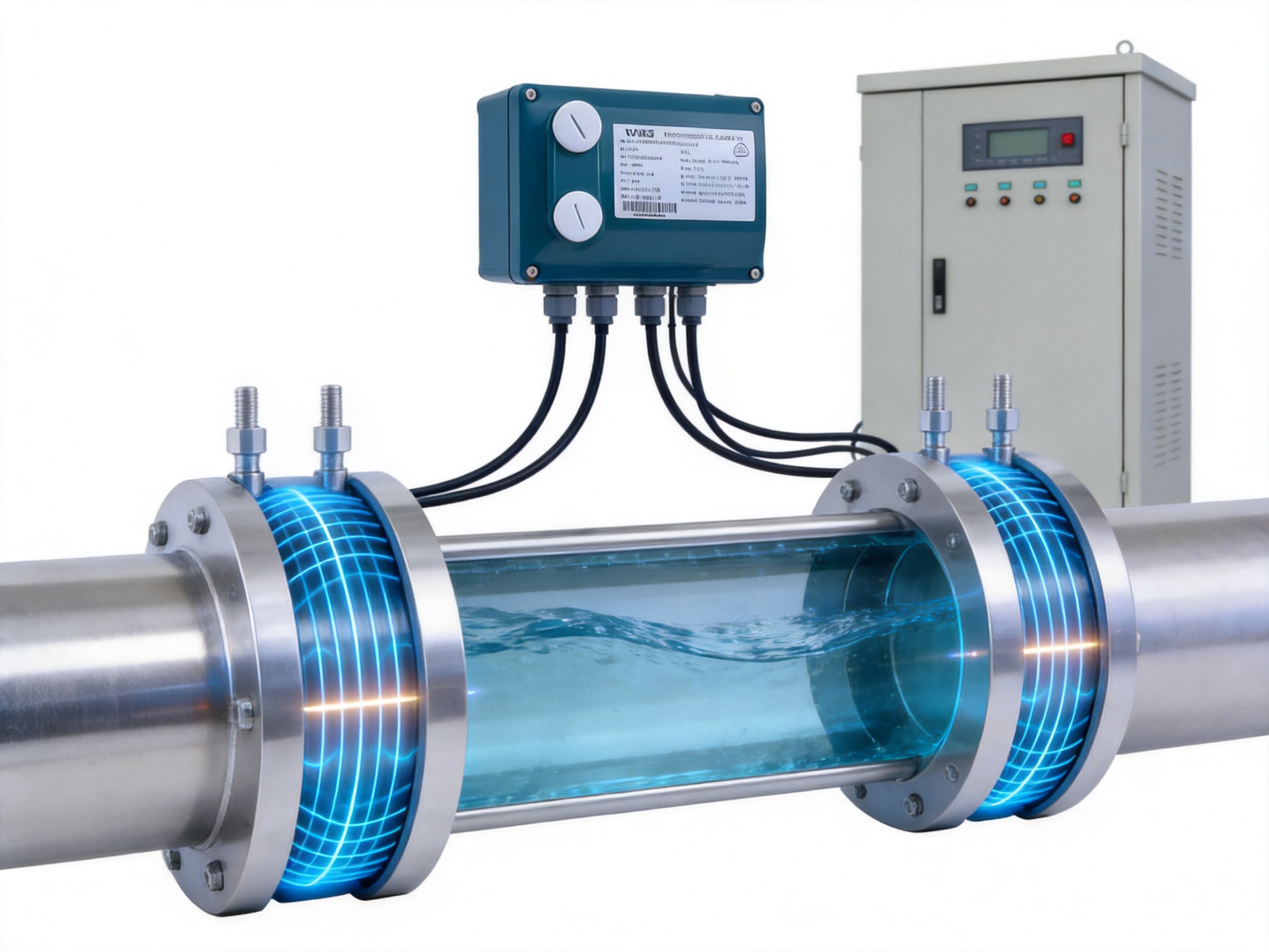
Inside the flowmeter, coils create a controlled magnetic field across the tube. Electrodes positioned in the measuring section detect the small voltage generated as the conductive medium passes through the field. The converter then processes this signal, applies the relevant calibration parameters and converts it into a volumetric-flow output.
Because the measurement depends on the velocity of a conductive liquid rather than on mechanical displacement, the technology is largely independent of fluid density, viscosity, pressure and temperature. This independence applies within the specified operating range and assumes that the medium conductivity, installation conditions and material compatibility requirements are satisfied.
The electromagnetic principle is well suited to water, beverages, sugar solutions, wash water, cooling water, conductive chemicals and many viscous liquids. It can also be used with certain slurries when the solids content, conductivity, lining and electrode materials are appropriate. Non-conductive liquids such as many oils, hydrocarbon products and some solvents are not suitable for standard electromagnetic measurement.
Product Configuration and Principal Specifications
The VE13 is a compact hygienic and small-bore electromagnetic flowmeter. It is available for nominal diameters from DN10 to DN125, corresponding approximately to 3/8 inch through 5 inches. This range allows the same measurement principle to be applied to laboratory-scale process branches, dosing lines, utility connections, skid-mounted equipment and larger hygienic transfer lines.
| Parameter | Specification | Engineering Significance |
|---|---|---|
| Measuring principle | Electromagnetic measurement based on Faraday’s law | Non-mechanical measurement of conductive liquids |
| Product type | Compact hygienic small-bore flowmeter | Suitable for restricted spaces and equipment packages |
| Measured media | Conductive liquids and selected slurries | Applicable to water, beverages, viscous liquids and compatible chemicals |
| Accuracy | ±0.5% of rate | Supports process monitoring, transfer measurement and dosing applications |
| Repeatability | Typically 0.16% of rate | Useful for repeatable batch and control operations |
| Flow velocity range | 0.3 to 10 m/s | Provides flexibility across low and relatively high process velocities |
| Nominal diameter | DN10 to DN125 | Covers many compact process and utility lines |
| Process connections | Threaded and Tri-Clamp | Supports industrial and hygienic installation requirements |
| Nominal pressure | 1 MPa | Suitable for specified low- and medium-pressure process systems |
| Medium temperature | -40 to +200 °C, configuration dependent | Allows selection for different process and cleaning conditions |
| Protection class | IP65 | Protects the enclosure against dust and water jets under defined conditions |
| Body materials | 304, 316 or 316L stainless steel | Provides mechanical strength and corrosion resistance options |
| Lining materials | FEP or PFA | Supports chemical resistance and process compatibility |
| Electrode materials | 316L stainless steel, Hastelloy or titanium | Allows material selection for different liquids and chemical conditions |
| Outputs | 4-20 mA and pulse | Supports analog control, totalization and batch functions |
| Digital communication | Modbus RS-485 and HART | Enables configuration, diagnostics and system integration |
| Power supply | 24 V DC or 220 V AC | Fits common industrial and equipment-panel power architectures |
| Explosion protection | Ex d versions available | Supports designated hazardous-location applications when properly certified |
Actual performance depends on the selected size, lining, electrode material, process temperature, conductivity, installation arrangement and calibration. Engineering selection should therefore be completed using the complete operating data rather than relying only on nominal pipe size.
Advantages of the Unobstructed Full-Bore Design
Minimal Additional Pressure Loss
The VE13 does not require an internal rotor or restriction to generate a measurement signal. Its full-bore construction allows the medium to pass through the tube with practically no additional pressure loss attributable to the measuring device. This can be an important advantage in transfer lines, dosing systems and compact skids where every pressure drop affects pump sizing and energy consumption.
Reduced pressure loss also supports stable operation in systems that use low-pressure pumps, gravity-assisted transfer or sensitive process equipment. The flowmeter does not need to be treated as a significant hydraulic restriction when the installation is correctly sized and operated within the recommended velocity range.
Reduced Risk of Clogging
Small-bore process lines can be vulnerable to deposits and blockages, especially when liquids contain suspended particles, fibers, crystals or viscous components. A meter with a rotor or narrow internal passage may become less reliable as deposits build up. The unobstructed bore of the VE13 reduces this risk and helps maintain a consistent hydraulic profile.
This does not mean that every slurry or particulate-bearing liquid is automatically suitable. Conductivity, solids concentration, particle size, abrasion, settling behavior and cleaning practice must be evaluated. Nevertheless, the absence of moving internal parts gives the electromagnetic design a practical advantage over many mechanical alternatives in compatible applications.
No Mechanical Wear in the Measuring Principle
There are no bearings, gears, shafts or impellers in the VE13 measuring tube. The measurement signal is generated electronically, so the instrument does not experience mechanical wear in the same way as a turbine or positive-displacement device. This can extend service intervals and reduce the number of wear-related components that must be stocked or replaced.
The lack of moving parts is especially valuable in applications with frequent starts and stops, variable flow rates or liquids whose viscosity changes during production. Mechanical meters may require careful consideration of bearing lubrication, rotor friction and minimum operating conditions. An electromagnetic meter avoids these particular limitations, provided the liquid remains sufficiently conductive.
Hygienic Construction for Food, Beverage and Clean Process Applications
Hygienic process equipment must support cleaning, inspection and material compatibility. The VE13 can be supplied with stainless-steel construction and Tri-Clamp connections for applications where rapid disassembly and cleanable interfaces are required. The instrument is suited to lines carrying drinking water, beverages, sugar solutions, syrups, wash water and other conductive process liquids when the selected materials are compatible with the product and cleaning chemicals.
FEP and PFA lining options provide a chemically resistant internal surface between the process medium and the meter body. These fluoropolymer linings can be considered for liquids that may attack unprotected metal or where a stable, non-reactive wetted surface is needed. The choice between lining materials depends on temperature, chemical exposure, pressure, cleaning regime and mechanical requirements.
316L stainless-steel electrodes are a common choice for hygienic water and food-related services. Hastelloy or titanium electrodes may be selected when the medium presents greater corrosion risk or when a different electrode behavior is needed. Selecting the correct electrode material is important because the electrodes are directly exposed to the process liquid and form a critical part of the measurement circuit.
Hygienic installation also depends on the surrounding pipework. The flowmeter should be installed in a location that allows the tube to remain full during operation. Dead legs, unsuitable gaskets, poor drainage and incompatible cleaning procedures can compromise an otherwise well-designed instrument. The meter’s materials and connection type should be reviewed together with the complete sanitary piping system.

VE13 Hygienic Electromagnetic Flowmeter
Stable Measurement Under Changing Process Conditions
Many industrial liquids change during production. Temperature may rise during cleaning or processing, viscosity may vary with concentration, and pressure can fluctuate as valves open and close. In electromagnetic measurement, the flow signal is primarily related to liquid velocity, so moderate changes in density and viscosity do not directly alter the measurement in the way they can affect some mechanical technologies.
This process independence helps the VE13 maintain stable performance when measuring water, beverages, sugar solutions and viscous conductive liquids. The qualification is important: the liquid must remain within the specified conductivity range, the tube must be full, the electrodes must remain properly wetted and the installation must meet the manufacturer’s requirements.
The specified flow velocity range of 0.3 to 10 m/s provides flexibility for system design. Lower velocities may be useful for gentle transfer or controlled dosing, while higher velocities can support compact line sizing and faster transfer. The selected size should be checked against minimum and maximum operating flow, normal flow, start-up conditions and any potential low-flow periods.
Accuracy is specified at ±0.5% of rate, with typical repeatability of approximately 0.16% of rate. Accuracy and repeatability are different performance characteristics. Accuracy describes how close the measured value is to the actual reference value, while repeatability describes how consistently the meter produces the same result under repeated conditions. Both are important in production control and batch operations.
Converter Electronics and Signal Processing
The VE13 uses microprocessor-based electronics and programmable low-frequency rectangular excitation. This design controls the magnetic field, processes the electrode signal and helps separate the flow-related signal from electrical interference. Modern excitation technology is particularly useful in industrial environments where motors, variable-frequency drives, switching devices and long cable runs may introduce noise.
Surface-mount device and surface-mount technology construction support a compact converter design. These manufacturing methods allow electronic components to be placed efficiently and consistently on printed circuit boards. They also support repeatable assembly, reduced wiring complexity and improved suitability for compact instruments.
The electronics are designed to provide stable and repeatable operation under demanding process conditions. Signal processing can include configuration of measurement parameters, output scaling, flow direction handling and diagnostic functions, depending on the selected converter version. Engineers should specify the required display, output, communication and enclosure configuration during ordering.
The 4-20 mA output is widely used for process control. A control system can interpret the current signal as an instantaneous flow rate, while the pulse output can be used for totalization, batching or connection to a flow counter. These two outputs allow the meter to serve both continuous monitoring and discrete production functions.
Modbus RS-485 communication provides a practical digital interface for PLCs, supervisory systems and equipment skids. HART communication can support remote configuration and diagnostics in systems that use a compatible analog-instrumentation architecture. Digital communication reduces the need for local access when parameters must be reviewed or adjusted after commissioning.
Comparison with Other Flowmeter Technologies
No single flowmeter technology is ideal for every liquid. The principal advantage of the VE13 is that it combines electromagnetic measurement with hygienic connections, compact construction and an unobstructed bore. Its suitability should be assessed against the characteristics of the fluid and the objectives of the installation.
Compared with Turbine Flowmeters
Turbine flowmeters use a rotor that turns as liquid passes through the meter. They can provide useful accuracy for clean, low-viscosity liquids, but their moving parts can be affected by suspended solids, viscosity changes and mechanical wear. The rotor and bearings may also introduce pressure loss and require inspection.
The VE13 avoids these mechanical concerns. It is generally more tolerant of compatible viscous liquids and selected slurries, and it does not require a rotor to remain mechanically free. For hygienic beverage or sugar-solution lines, the full-bore electromagnetic design may also simplify cleaning and reduce the risk of internal mechanical contamination.
A turbine meter may still be preferable for non-conductive liquids or applications where a very low conductivity medium must be measured. The electromagnetic principle requires sufficient electrical conductivity, so technology selection must begin with the fluid properties.
Compared with Vortex Flowmeters
Vortex flowmeters measure the frequency of vortices formed behind an obstruction. They are often used for gases, steam and some liquids. However, they require a flow body in the stream and can be sensitive to flow-profile conditions, vibration and low-flow performance.
The VE13 has no bluff body or internal obstruction. This gives it a hydraulic advantage for conductive liquids and makes it well suited to applications where pressure loss and clogging are concerns. It is not a substitute for a vortex meter when gas or steam measurement is required, because electromagnetic meters are intended for conductive liquids.
Compared with Coriolis Flowmeters
Coriolis flowmeters can measure mass flow directly and may provide density information. They are powerful instruments for high-value process measurement, but they can be more expensive, heavier and more demanding to install, especially in larger line sizes or compact equipment.
The VE13 measures volumetric flow and is often a more economical and hydraulically open choice for conductive liquids where direct mass-flow measurement is not necessary. It can provide dependable flow measurement without the vibrating tubes used in Coriolis instruments. When a process requires direct mass flow, concentration calculation based on density or custody-transfer-level mass measurement, a Coriolis meter may be the better technology.
Compared with Ultrasonic Flowmeters
Ultrasonic flowmeters can be installed externally in some configurations, avoiding direct contact with the liquid. However, their performance may depend strongly on pipe condition, acoustic properties, installation geometry and the presence of entrained gas or suspended matter.
The VE13 provides a defined internal measuring tube and direct electrode-based signal acquisition. When the liquid conductivity is adequate and the line can be interrupted for installation, it offers a predictable integrated solution with sanitary connection options. An ultrasonic meter may be advantageous where non-invasive installation is essential or where the liquid is not conductive.
Compared with Rotameters
Metal-tube rotameters are simple and useful for local indication, purge systems and low-complexity flow monitoring. They may not offer the same level of digital communication, remote diagnostics or automated control integration as the VE13.
The VE13 is better suited to systems that require 4-20 mA, pulse, Modbus or HART communication. It also provides electronic totalization and integration with PLC or DCS platforms, subject to the selected converter. A rotameter may remain the practical option when visual indication and low initial complexity are the main objectives.
Installation Considerations for Reliable Performance
Correct installation is essential for electromagnetic measurement. The measuring tube should remain full during operation. A partially filled tube can expose the electrodes to air and cause unstable or incorrect readings. For this reason, the meter is often installed in a vertical or upward-flowing section, or in another location where the process conditions maintain a full tube.
The pipeline should be designed to prevent air accumulation near the meter. Entrained gas bubbles can affect signal stability, especially when the liquid velocity changes rapidly. If air release is possible, the installation may require suitable venting, upstream conditioning or a different meter location.
The flowmeter should be aligned with the pipeline and installed without excessive mechanical stress. Gaskets must be correctly positioned so that they do not protrude into the measuring bore. For Tri-Clamp installations, compatible clamps, gaskets and ferrules should be used. Hygienic systems should also consider drainability and the avoidance of unnecessary pockets where product or cleaning liquid could remain.
Grounding and electrical bonding are important because the instrument detects a relatively small induced voltage. The installation should follow the grounding instructions for the specific liner and pipe material. Poor grounding, electrical noise or an unsuitable cable arrangement can reduce measurement stability even when the hydraulic installation is correct.
The meter should be located away from strong sources of electromagnetic interference where practical. Variable-frequency drives, large motors, transformers and high-power switching equipment can affect low-level measurement signals. Shielded cables, correct cable routing and proper grounding help protect the signal path.
Before commissioning, the user should confirm the configured pipe size, measurement range, flow direction, conductivity, output scaling, communication parameters and alarm settings. The meter should be filled with the actual process liquid before zero verification. A zero adjustment performed while the tube is not completely full or while flow is present can produce an incorrect reference.
Material Selection and Process Compatibility
Material selection must be based on the complete process environment rather than on the liquid name alone. A beverage, cleaning solution or chemical additive may have different effects depending on concentration, temperature, exposure time and the presence of other compounds.
Stainless-steel body options include 304, 316 and 316L. The selected grade should match the corrosion environment, hygienic requirements and mechanical design. 316L is commonly considered for sanitary and more corrosion-sensitive services, but the suitability of any grade must be confirmed against the actual medium and cleaning chemicals.
FEP and PFA lining options provide a barrier between the liquid and the meter body. Their temperature and chemical-resistance characteristics should be reviewed with the process engineer. A high-temperature cleaning cycle, for example, may impose different requirements from normal product operation.
Electrode selection is equally important. 316L stainless steel may be appropriate for many water and food applications. Hastelloy can be considered for more aggressive chemical services, while titanium may be selected for particular corrosive environments. The best choice depends on chloride concentration, acidity, alkalinity, oxidizing conditions, temperature and cleaning chemistry.
The supplied temperature range is -40 to +200 °C depending on configuration. The maximum permissible temperature is not necessarily the same for every combination of liner, electrode, body, connection and converter. A complete datasheet review is required before applying the meter to hot process liquids or high-temperature cleaning procedures.
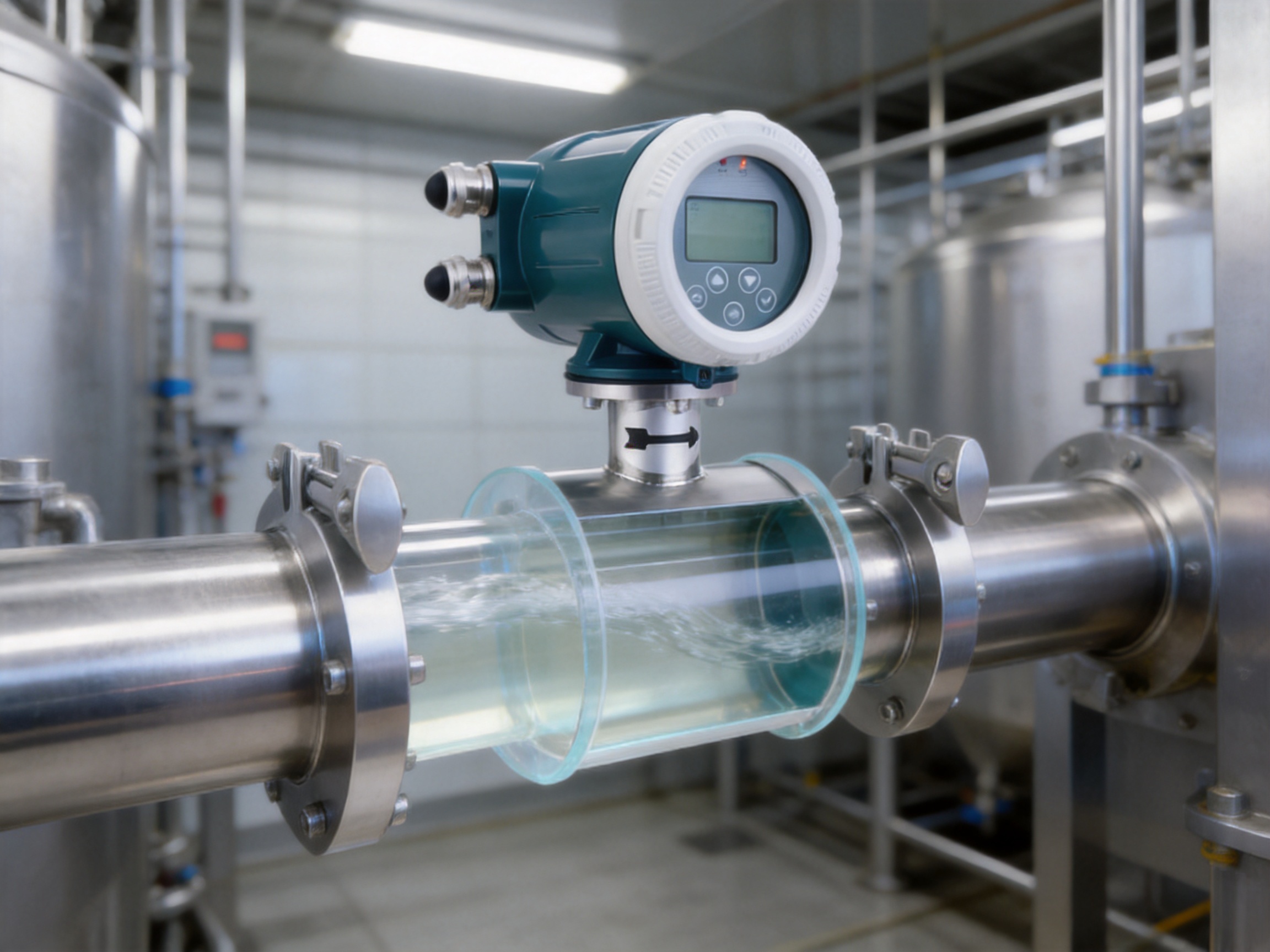
Outputs, Communication and Control-System Integration
Industrial flowmeters are increasingly expected to provide more than a local reading. The VE13 supports 4-20 mA and pulse outputs for common control and totalization functions. The analog signal can represent the configured flow range, while the pulse output can represent a defined volume or be used for batch counting.
These outputs make the meter suitable for connection to PLCs, DCS systems, batch controllers and electronic totalizers. In a beverage transfer line, for example, the analog output can be used to monitor line flow while the pulse output records transferred volume. In a cleaning skid, the instrument can provide flow confirmation to ensure that a required circulation rate has been achieved.
Modbus RS-485 communication enables digital data exchange over an industrial network. Depending on the system architecture and instrument configuration, operators may use the communication interface to read flow rate, totalized flow, status information and diagnostic parameters. HART communication can provide another route for remote configuration and service access.
Digital communication can reduce commissioning time because technicians do not always need to access the instrument directly to review settings. It also supports centralized asset management in larger facilities. Communication protocols should be specified early so that address settings, wiring, termination, power supply and control-system compatibility are included in the project design.
IP65 protection is provided for the stated enclosure configuration. The installation environment should still be assessed for washdown intensity, chemical exposure, ambient temperature, vibration and outdoor weather. Where the instrument is installed in a location with more severe environmental conditions, the enclosure and mounting arrangement should be reviewed carefully.
Explosion-Proof Options and Industrial Application Range
Ex d explosion-proof versions are available for designated hazardous locations, subject to the applicable model and regional certification. Hazardous-area selection must be based on the site classification, gas or dust group, temperature class, ambient conditions and local regulations.
An explosion-proof option does not eliminate the need for correct installation. Cable glands, conduit systems, grounding, inspection procedures and electrical barriers must comply with the project’s hazardous-area requirements. The user should verify the exact certification markings and permitted installation conditions before ordering or commissioning the instrument.
In non-hazardous plants, the standard compact configuration may be sufficient. In chemical and general industrial facilities, the meter can be configured with suitable liner and electrode materials for conductive raw materials, additives and viscous process liquids. In utilities and OEM equipment, the compact body can be integrated into cooling-water, wash-water, cleaning-solution and treatment-skid systems.
Typical Applications
Beverage and Liquid Food Transfer
VE13 installed in a stainless-steel line with Tri-Clamp connections can measure syrups, beverages, process water and other conductive liquids. Its unobstructed bore supports low additional pressure loss, while the sanitary connection can simplify line disassembly and inspection.
For viscous products, the process engineer should confirm that the operating velocity remains within the recommended range and that the selected liner and electrode materials are compatible with the product. Cleaning-in-place or manual-cleaning procedures must also be reviewed against the meter’s temperature and chemical limits.
Water and Utility Systems
Cooling water, wash water, utility water and treatment liquids are common electromagnetic-flowmeter applications. The technology is well suited to these services because water normally has adequate conductivity, and the measurement is not strongly affected by density or viscosity changes.
Compact OEM skids may use the VE13 where available space is limited. The threaded version can support compact pipe layouts, while the Tri-Clamp version can be used when hygienic disassembly is required. The 4-20 mA and pulse outputs allow the meter to connect to a local controller or a plant-wide automation system.
Chemical Dosing and Blending
Conductive chemical raw materials, additives and blending liquids can be measured when the selected wetted materials are compatible. The lack of moving parts is useful in applications where fluid viscosity changes or where small solids could interfere with mechanical meters.
For aggressive chemicals, material compatibility must be verified with particular care. Lining, electrode, gasket and connection materials should all be considered. The chemical concentration, temperature, pressure and cleaning or flushing procedure should be included in the selection documentation.
Compact Treatment and Process Equipment
Package units and treatment skids often require several instruments in a small footprint. A compact electromagnetic flowmeter can provide reliable flow information without a large straight mechanical assembly or a significant internal restriction. Modbus or HART communication can reduce panel wiring and simplify integration into the equipment controller.
OEM builders can also benefit from standardized configuration options. Different power supplies, process connections, output combinations and electrode materials allow the meter to be adapted to several skid designs while retaining a common measurement principle.
Manufacturing Strengths and Engineering Support
Product performance depends not only on the measurement principle but also on the consistency of manufacturing, calibration and quality control. Jiangsu VNER Electronic Technology Co., Ltd. is a specialized industrial flowmeter manufacturer based in Yangzhou, China. Since 2011, the company has developed solutions for electromagnetic, Coriolis, vortex, swirl, turbine, thermal mass, ultrasonic and rotameter applications.
The company operates approximately 23,000 square meters of modern facilities across three plants and has a technical team of more than 150 people. This production and engineering base supports the development and manufacture of instruments for liquid, gas and slurry measurement. It also provides a foundation for managing different process connections, wetted materials, electronics packages and application requirements.
More than 2,000 engineering projects have been delivered in over 30 countries. This project experience is valuable because flowmeter selection frequently involves more than choosing a nominal diameter. Installation conditions, conductivity, pressure, temperature, liner compatibility, electrode selection, hazardous-area requirements and control-system interfaces all influence the final configuration.
The company supports EPC contractors, end users and OEM partners in industries including oil and gas, petrochemical, polysilicon, power, water and wastewater. Although the VE13 is focused on hygienic and small-bore conductive-liquid measurement, experience across these industrial sectors contributes to a broader understanding of instrumentation integration, process reliability and site requirements.
In-House Calibration
In-house calibration is an important manufacturing capability for flow instrumentation. A controlled calibration process helps verify the relationship between actual flow and the instrument’s output. It also supports product consistency, traceability and documentation for project acceptance.
Calibration should be performed using procedures and reference standards appropriate to the instrument range and accuracy requirements. The final result depends on the meter size, selected range, test medium, reference equipment and applicable quality procedures. For projects requiring formal calibration documentation, the required certificate and test conditions should be specified before production.
Engineering-Driven Sizing and Selection
A flowmeter should not be selected solely by matching the connection size to the pipe. The normal, minimum and maximum flow rates must be considered together with conductivity and velocity. A meter that is oversized may operate at an unnecessarily low velocity, while an undersized meter may create excessive velocity or exceed the application’s pressure and noise limitations.
Engineering-driven selection helps identify the correct nominal diameter and configuration. The process data should include liquid composition, minimum conductivity, operating temperature, maximum pressure, expected solids, cleaning conditions, connection standard, power supply, output requirements and hazardous-area classification where applicable.
VNER’s product range across several measurement technologies also allows engineers to evaluate the most appropriate principle for a particular service. Conductive liquids may be assigned to electromagnetic measurement, while gases, steam, non-conductive liquids or direct mass-flow applications may require other technologies in the company’s portfolio.
Automated and Consistent Manufacturing
Increasing automation in manufacturing can improve repeatability in assembly and reduce variation between instruments. Surface-mount electronics production, controlled wiring, enclosure assembly and systematic inspection all contribute to product consistency. Automated processes are especially valuable when a manufacturer supplies multiple configurations for different international projects.
Manufacturing quality also depends on the control of mechanical dimensions, liner installation, electrode placement, coil performance and converter configuration. These factors influence the stability of the measurement signal. A structured production process helps ensure that the finished instrument matches the engineering design and documented specifications.
Certified Quality Processes and Traceability
Certified quality processes provide a framework for documenting production, inspection and calibration activities. Traceability is particularly important for EPC projects and regulated industries, where customers may require evidence of material selection, inspection results, calibration performance and final configuration.
For the VE13, traceability can help connect the product identification, selected materials, electrical configuration and calibration record. Customers should confirm the specific documentation package required for their project, including certificates, inspection records, hazardous-area documents and regional conformity information.
How the VE13 Creates Value Compared with Competing Designs
The VE13’s competitive value comes from the combination of several practical features rather than from one specification alone. The instrument offers electromagnetic measurement, a full-bore design, compact dimensions, hygienic connection options, corrosion-resistant materials, modern electronics and multiple control-system interfaces.
Compared with a basic mechanical flowmeter, it can reduce concerns associated with moving parts, wear and internal obstruction. Compared with a larger or more complex mass-flow instrument, it can offer a compact and economical solution when volumetric flow is sufficient. Compared with a simple local indicator, it provides remote outputs and digital communication for automation.
The availability of different body, lining and electrode materials gives designers more flexibility than a single fixed configuration. Stainless-steel options support hygienic and industrial construction, while FEP and PFA linings and special electrodes broaden the range of compatible media. Threaded and Tri-Clamp connections allow the same basic instrument concept to serve both compact industrial lines and sanitary systems.
Another advantage is the manufacturer’s ability to combine product manufacturing with engineering support. A flowmeter can perform well in the laboratory but fail to deliver reliable field results if the size, grounding, full-pipe condition or materials are wrong. Application-based selection and project experience help reduce this risk.
Maintenance and Long-Term Reliability
The VE13’s non-mechanical measuring principle reduces routine maintenance associated with moving components. There is no rotor to lubricate and no bearing assembly to replace. Maintenance attention should instead focus on process compatibility, electrical connections, grounding, installation integrity and the condition of the liner and electrodes.
If the process liquid can deposit solids or form a coating, the electrodes and measuring tube should be included in the plant’s inspection plan. A coating may change the electrical contact with the liquid and affect signal quality. The appropriate cleaning method depends on the deposited material and the selected liner and electrode materials.
Electrical maintenance should include inspection of cable glands, terminals, grounding connections and enclosure seals. In hazardous areas, inspection must follow the applicable Ex maintenance procedures. Any repair or replacement involving the converter or enclosure should preserve the required protection and certification status.
Periodic verification may be appropriate for critical dosing, batching or transfer applications. The frequency can be established according to plant quality procedures, process risk, operating history and regulatory requirements. A stable operating history may support a risk-based interval, while demanding or regulated services may require more frequent checks.
Selection Guide for Project Engineers
Before specifying the VE13, engineers should collect the following process information:
Liquid name, composition and electrical conductivity.
Minimum, normal and maximum flow rates.
Pipe size and required flow velocity.
Operating and cleaning temperatures.
Normal and maximum process pressure.
Presence, concentration and particle size of suspended solids.
Required body, lining, electrode and gasket materials.
Threaded or Tri-Clamp connection requirements.
Applicable DIN, ANSI or ASME connection standards.
Power supply, output and communication requirements.
Ambient conditions, enclosure requirements and hazardous-area classification.
Calibration documents, certifications and inspection requirements.
Conductivity is one of the most important checks. If the liquid does not have adequate conductivity, the electrodes cannot obtain a sufficiently stable signal. The user should obtain the minimum conductivity under the actual process conditions, not only a typical laboratory value.
Flow range should be checked against the recommended velocity range of 0.3 to 10 m/s. The normal operating point should ideally be comfortably within the selected range rather than near an extreme boundary. This improves resolution during normal operation and leaves capacity for process variation.
Connection selection should reflect both the pipe standard and maintenance philosophy. Threaded connections can reduce size and installation complexity, while Tri-Clamp connections may be better for sanitary lines, frequent inspection and rapid equipment disassembly.
Quality, Project Delivery and Global Application
Industrial customers often need a supplier that can support the complete path from inquiry to commissioning. This includes technical clarification, sizing, configuration, production, calibration, documentation and after-sales communication. A manufacturer with experience in EPC projects and OEM supply can help align the instrument with broader project schedules and documentation systems.
VNER’s work across more than 30 countries demonstrates experience with international industrial requirements. Different regions may require different connection standards, power supplies, conformity documents, communication practices and hazardous-area approvals. The VE13 can be configured around these requirements when the applicable options are confirmed during the inquiry stage.
The company’s broad product portfolio is another practical strength. Electromagnetic meters address conductive liquids, while other flowmeter families are available for gas, steam, mass-flow, thermal, ultrasonic and variable-area applications. This enables customers with multiple measurement duties to work with a supplier that understands the differences between flow technologies rather than forcing every application into one product category.
For OEM partners, repeatable manufacturing and configuration control are particularly important. A package-unit builder may need identical instruments across multiple skids, with consistent wiring, range settings, connection dimensions and documentation. Controlled production, in-house calibration and traceability can support this type of standardized supply.
Recommended Application Boundaries
The VE13 is recommended for electrically conductive liquids and selected slurries. It is especially appropriate where the process requires a full-bore instrument, low additional pressure loss, compact installation, hygienic connections or integration with industrial control systems.
It should not be selected without further review for non-conductive liquids, gas, steam or applications requiring direct mass-flow measurement. It may also require special evaluation for highly abrasive slurries, liquids with significant entrained gas, severe pulsating flow, extremely low conductivity or processes with unusual chemical exposure.
The stated IP65 protection, 1 MPa nominal pressure and temperature range of -40 to +200 °C are configuration-dependent design parameters. The final product must be matched to the complete process and environmental conditions. Certification claims such as ATEX and explosion protection are also model- and region-dependent and should be verified using the applicable product documentation.
Q&A: Frequently Asked Questions
What type of liquid can the VE13 measure?
The VE13 is designed for electrically conductive liquids and selected slurries. Typical examples include water, drinking water, beverages, sugar solutions, viscous conductive liquids, cooling water, wash water, cleaning solutions and compatible chemical materials. The liquid must meet the required conductivity and material-compatibility conditions.
Can the VE13 measure oil or other hydrocarbon liquids?
Most oils and many hydrocarbon liquids are non-conductive and are therefore not suitable for standard electromagnetic measurement. The actual conductivity should be checked before selection. If the medium is not sufficiently conductive, another flowmeter technology should be considered.
Does the flowmeter contain a moving rotor?
No. The VE13 uses electromagnetic induction and has no moving or intrusive measuring parts. This helps reduce mechanical wear, internal obstruction and additional pressure loss.
What is the accuracy of the VE13?
The stated accuracy class is ±0.5% of rate, with typical repeatability of approximately 0.16% of rate. Final performance depends on the selected configuration, calibration conditions, conductivity, installation and operating range.
What pipe sizes are available?
The nominal diameter range is DN10 to DN125, approximately 3/8 inch to 5 inches. The correct size should be selected using minimum, normal and maximum flow rates rather than pipe size alone.
Are sanitary connections available?
Yes. The VE13 can be supplied with Tri-Clamp sanitary connections. Threaded connections are also available for compact industrial installations. Connection standards and dimensions should be confirmed for each project.
Can the meter be used in food and beverage applications?
It can be used for compatible conductive liquids in food and beverage lines, including beverages, syrups, sugar solutions and process water. The selected stainless-steel grade, lining, electrode, gasket and connection configuration must be compatible with the product and the cleaning procedure.
What outputs are provided?
The standard output specification includes 4-20 mA and pulse outputs. These can be used for continuous flow indication, PLC or DCS integration, totalization and batch control. Modbus RS-485 and HART communication are also available as digital options.
What power supplies can be used?
Configurations are available for 24 V DC or 220 V AC power supplies. The required supply should be specified before production so that the converter is correctly configured for the installation.
Can the VE13 be used in hazardous areas?
Ex d explosion-proof versions are available for designated hazardous locations, subject to the applicable model and regional certification. The site classification, certification markings, cable-entry method and installation requirements must be verified before ordering.
What is the maximum process temperature?
The stated medium temperature range is -40 to +200 °C depending on configuration. The permissible temperature must be confirmed for the selected liner, electrodes, body, connections and converter. Cleaning temperatures may also require separate review.
How should the meter be installed?
The measuring tube should remain full during operation. The installation should minimize air accumulation, avoid excessive vibration, use correct grounding and maintain suitable upstream and downstream conditions. Gaskets must not extend into the bore, and the meter should be aligned correctly with the pipeline.
Does the meter require frequent maintenance?
The absence of moving parts reduces mechanical maintenance. Routine attention should focus on electrical connections, grounding, enclosure condition, liner and electrode condition, process deposits and periodic verification where required by the application.
Why is conductivity important?
The electromagnetic signal is generated by the movement of a conductive liquid through a magnetic field. If conductivity is too low, the electrode signal may be weak or unstable. The minimum conductivity should be confirmed under actual process conditions.
Can VNER support custom configurations?
The product information indicates support for customized high-precision industrial instruments. Configuration may include diameter, connection, body material, lining, electrode material, power supply, outputs, communication and certification options. Final availability should be confirmed with the manufacturer for the specific project.
Conclusion
The VE13 Hygienic Electromagnetic Flowmeter is a practical solution for compact process lines carrying conductive liquids. Its Faraday-based measuring principle eliminates moving parts, while the full-bore design minimizes additional pressure loss and reduces the risk of internal blockage. Stainless-steel construction, FEP or PFA lining, selectable electrode materials and Tri-Clamp connections make it suitable for hygienic and chemically demanding applications when the materials are correctly selected.
Its ±0.5% accuracy, typical 0.16% repeatability, 0.3 to 10 m/s velocity range and DN10 to DN125 size range support a broad selection of small-bore measurement duties. The combination of 4-20 mA, pulse, Modbus RS-485 and HART interfaces allows the instrument to integrate into modern control and monitoring systems.
The product’s advantages over many competing designs are strongest where conductive liquids, low pressure loss, cleanable connections, compact dimensions and low mechanical maintenance are important. It is not intended for every fluid or every measurement objective, but it offers a well-balanced alternative to turbine, vortex, ultrasonic, rotameter and Coriolis technologies in its defined application range.
Behind the product is a manufacturer with specialized flow-measurement experience, approximately 23,000 square meters of facilities, three plants, a technical team of more than 150 people, in-house calibration, certified quality processes, engineering-based sizing and international project experience. These capabilities support consistent production and help customers select, configure and deploy the flowmeter for reliable long-term service.
References
1. Faraday, M. Experimental Researches in Electricity, foundational work concerning electromagnetic induction.
2. International Electrotechnical Commission. Electromagnetic flowmeter measurement principles and performance considerations.
3. International Organization for Standardization. Hygienic design principles for equipment used in food and beverage processing.
4. International Electrotechnical Commission. Degrees of protection provided by enclosures, including IP protection classifications.
5. International Electrotechnical Commission. Requirements and certification principles for electrical equipment used in explosive atmospheres.
6. Manufacturer technical information for the VE13 Hygienic Electromagnetic Flowmeter, including specifications, materials, connections, outputs and application guidance.
7. Manufacturer quality and engineering information concerning electromagnetic, Coriolis, vortex, swirl, turbine, thermal mass, ultrasonic and variable-area flow measurement products.
Product: VE13 Hygienic Electromagnetic Flowmeter

We offer all our products and services at international standards.
Products
Contact Information
-

+86-18652789521
+86-18052582295
+86-0514-83633600 / 83633900 -

+86-0514-83633600 / 83633900
-

shawn@vnerflow.com
info@vnerflow.com -

No. 11 Xingye Road, Chenji Town Industrial Park, Yizheng, Yangzhou, China
