
 0
 EN
 English
 عربى
 Español
 русский
If you need any help, please feel free to contact us
Home / Author / Ren Xiaotong — Technical Sales Engineer for Gas Flow Meters / Small-Pipe Clamp-On Ultrasonic Flow Measurement for Industrial Systems
Small-Pipe Clamp-On Ultrasonic Flow Measurement for Industrial Systems
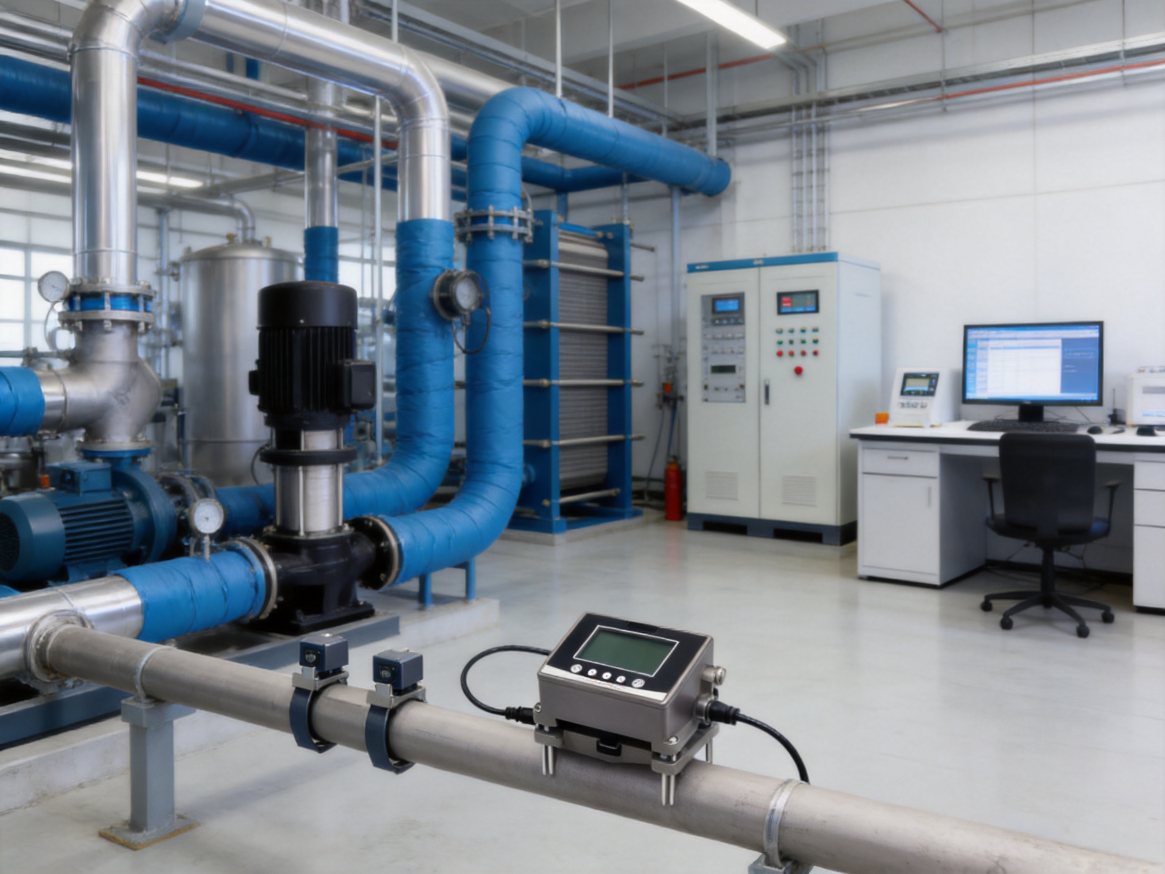
Reliable flow measurement is essential wherever water, thermal energy, or industrial process liquids must be monitored, controlled, balanced, or optimized. However, installing a conventional inline flow meter is not always practical. Cutting a pipeline may require a production shutdown, draining the system, welding new flanges, obtaining permits, and scheduling specialized labor. In many existing facilities, there may also be insufficient straight-pipe length, limited installation space, or a strong requirement to avoid contact between the instrument and the process liquid.
The VNFT211 clamp-on ultrasonic flow meter provides a practical solution for these conditions. Designed specifically for small-diameter pipelines from DN15 to DN65, it measures liquid flow from outside the pipe. Its external transducers are clamped onto the pipe surface, allowing measurement without pipe cutting, process interruption, pressure loss, or direct contact with the medium.
Based on the transit-time ultrasonic principle, the instrument calculates flow velocity by comparing the travel time of ultrasonic signals moving upstream and downstream through the pipe wall and liquid. The difference between the two transit times is proportional to the velocity of the liquid. After processing the signal and applying the configured pipe and medium parameters, the meter displays instantaneous flow, accumulated flow, status information, and alarms.
This article examines the operating principle, technical design, installation advantages, industrial applications, communication functions, manufacturing strengths, and selection considerations of the VNFT211. It also explains why a small-pipe clamp-on instrument can offer important advantages over conventional inline meters and how Jiangsu Vner Electronic Technology Co., Ltd. supports industrial customers with engineering, manufacturing, calibration, and application expertise.
1. The Need for Non-Intrusive Flow Measurement
Traditional flow meters are often installed directly into a pipeline. Depending on the technology, this may involve flanges, threaded connections, insertion fittings, welding, gaskets, or pipe modification. Such arrangements can provide excellent long-term measurement performance, but they also introduce installation requirements that may be difficult to meet in operating facilities.
Many water, HVAC, utility, laboratory, and process systems already have completed pipelines. These systems may not have an available shutdown window, and the liquid inside the pipe may be hot, pressurized, chemically treated, or essential to production. Removing a section of pipe for meter installation can therefore create safety, scheduling, and cost challenges.
A clamp-on flow meter avoids most of these difficulties. The pipeline remains intact, and the transducers are installed on the external surface. Because the measuring components do not protrude into the flow path, the instrument does not create an obstruction or additional permanent pressure drop. This makes clamp-on ultrasonic measurement especially useful for retrofit projects, temporary audits, verification work, and systems where process contamination must be avoided.
For small pipes, the challenge is greater because the available acoustic path is shorter and the pipe wall, lining, fittings, and liquid characteristics have a stronger influence on the signal. The VNFT211 is designed around the requirements of DN15–DN65 pipelines, providing a dedicated solution for compact piping networks instead of treating small pipes as an afterthought.
1.1 Common Problems with Conventional Installation
An inline flow meter may require the following activities:
- Stopping the process or isolating the pipeline.
- Draining or depressurizing the pipe.
- Cutting and preparing the pipeline.
- Installing flanges, couplings, or threaded connections.
- Providing sufficient straight pipe length.
- Testing the modified system for leakage.
- Restoring insulation, coatings, or pipe supports.
- Recommissioning the system after installation.
These activities can significantly increase the total project cost beyond the purchase price of the meter itself. In contrast, an external clamp-on instrument can normally be installed while the system remains in operation, provided that the application meets the specified liquid, pipe, temperature, and signal conditions.
1.2 Why Small Pipes Require a Dedicated Solution
Small-diameter pipelines are common in building services, equipment skids, packaged systems, laboratory installations, pilot plants, and utility branches. Their compact dimensions can make conventional meter installation difficult. A standard inline meter may occupy too much space or require pipe reducers and additional fittings that disturb the flow profile.
The VNFT211 supports pipe sizes from DN15 to DN65 and uses external transducers suitable for this range. Its compact measurement concept helps engineers monitor branch lines, equipment connections, and small-diameter water circuits without redesigning the piping layout.
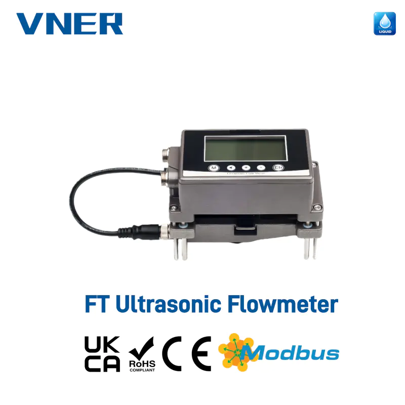
VNFT Clamp-On Ultrasonic Flow Meter
2. Operating Principle of the VNFT211
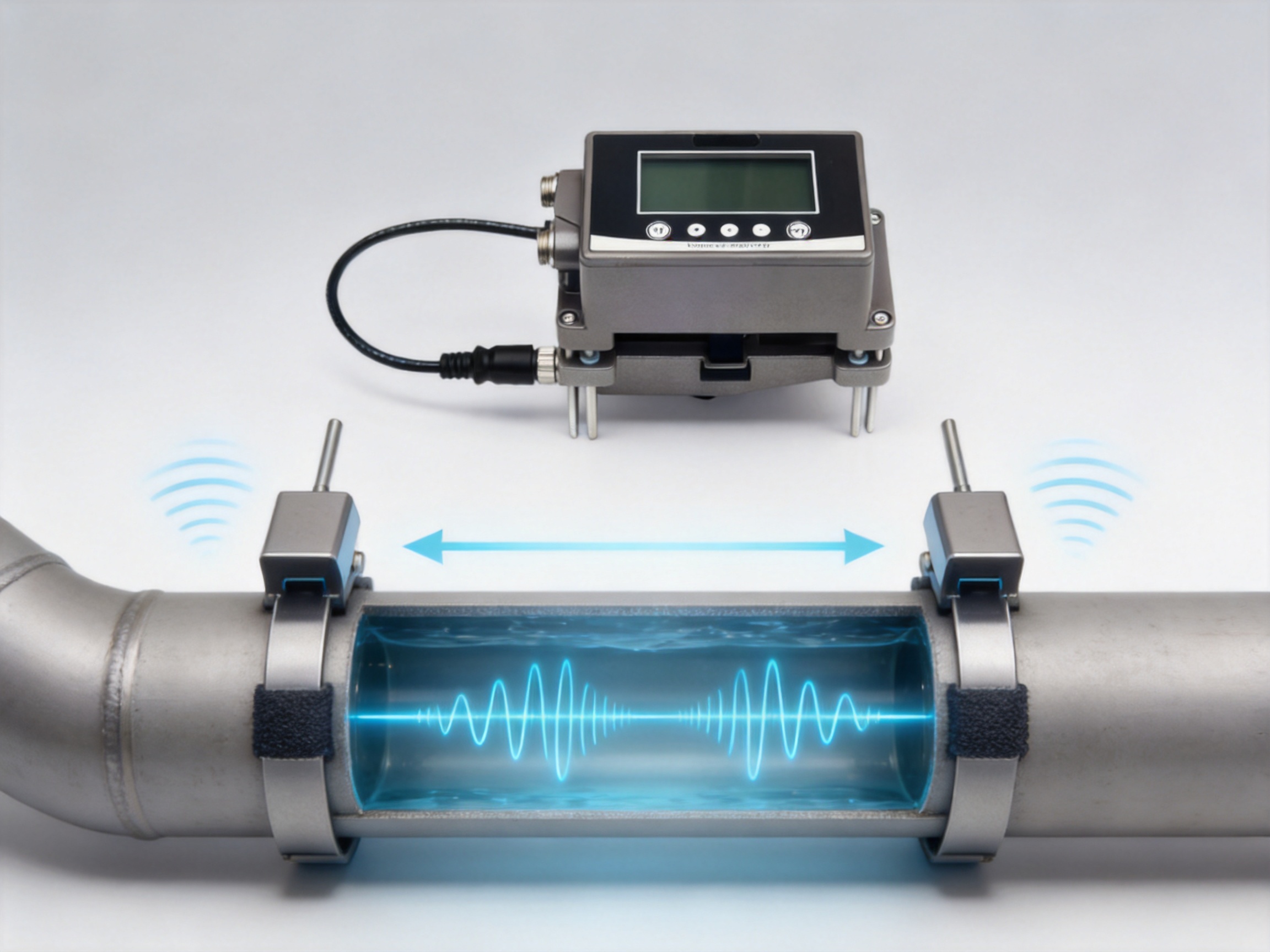
The VNFT211 uses transit-time ultrasonic measurement. Two ultrasonic transducers are positioned on the outside of the pipe. One transducer transmits an ultrasonic signal in the direction of flow, while the other transmits a signal against the direction of flow. The instrument measures the time required for the signals to travel between the transducers.
When liquid is stationary, the upstream and downstream transit times are nearly equal. When liquid flows through the pipe, the signal traveling with the liquid moves slightly faster, while the signal traveling against the liquid moves slightly slower. The difference between these transit times is related to the average liquid velocity along the acoustic path.
The meter uses this relationship to calculate flow velocity and volumetric flow. The calculation also considers the configured pipe diameter, pipe material, wall thickness, liquid properties, transducer arrangement, and acoustic path. Correct input parameters and careful transducer positioning are therefore important for achieving the best measurement result.
Because the transducers remain outside the pipe, the liquid does not contact the sensor assemblies. This is a significant advantage for clean water and other compatible single-phase liquids where maintaining process integrity is important.
2.1 Measurement Without Process Contact
The non-contact design provides several practical benefits. There is no wetted electrode, turbine rotor, vortex obstruction, or internal probe in the flow path. The meter is therefore not dependent on corrosion-resistant wetted materials in the same way as an inline sensor, and it does not introduce moving parts into the pipe.
The absence of internal components also simplifies maintenance. Operators can inspect, reposition, or remove the external transducers without opening the pipeline. This can be particularly valuable in systems that carry treated water, chilled water, heating water, or other liquids where draining the line would be inconvenient.
2.2 Measurement Conditions
The VNFT211 is intended for water and other single-phase liquids without solid particles or significant impurities. The liquid must provide a suitable acoustic path between the transducers. Air pockets, large quantities of suspended solids, heavy contamination, or surface freezing can interfere with ultrasonic signal transmission and should be considered during application review.
The specified liquid temperature range is 0 to 115 °C, with the condition that the pipe surface must not be frozen. Ambient operating temperature is –10 to 60 °C. These ranges allow the instrument to serve ordinary water systems, HVAC circuits, heating systems, and many industrial utility applications.
3. Principal Technical Specifications
The following table summarizes the main technical characteristics of the VNFT211 clamp-on ultrasonic flow meter.
| Parameter | Specification |
|---|---|
| Model | VNFT211 |
| Measurement principle | Transit-time ultrasonic measurement |
| Installation method | External clamp-on transducers |
| Pipe size | DN15–DN65 |
| Compatible pipe materials | Metal pipes and rigid plastic pipes including PVC, PP, and PVDF |
| Applicable liquids | Water and other single-phase liquids without solid particles or impurities |
| Liquid temperature | 0 to 115 °C |
| Accuracy | ±2%; up to ±1% after calibration |
| Low-velocity cutoff | Factory setting of 0.08 m/s |
| Response time | 0.5–60 seconds, adjustable |
| Display | 256 × 128 high-resolution LCD |
| Power supply | 10–24 VDC |
| Power consumption | Less than 3 W |
| Standard outputs | 4–20 mA and Modbus RS485 |
| Optional outputs | Pulse output OCT and relay alarm output |
| Enclosure protection | IP65 |
| Ambient temperature | –10 to 60 °C |
| Relative humidity | 35–85% RH, non-condensing |
The specifications demonstrate that the VNFT211 is more than a basic portable flow indicator. It combines local display, industrial communication, analog output, optional pulse output, alarm capability, data storage, and protection functions in a compact low-power instrument.
4. Advantages Over Conventional and Competing Solutions
Flow meter selection should be based on the complete installed cost and operating requirement rather than only on the instrument purchase price. The VNFT211 offers advantages in several areas: installation, process continuity, maintenance, integration, and application flexibility.
4.1 No Pipe Cutting or Process Shutdown
The greatest benefit is the external installation method. Operators can mount the transducers on an existing pipeline without cutting the pipe or installing a spool piece. This reduces the need for shutdown planning and allows the instrument to be used in facilities where continuous operation is important.
For retrofit projects, the clamp-on arrangement can avoid the cost of pipe modifications, welding, isolation valves, drainage, and recommissioning. It is also useful when the pipeline is buried, difficult to access internally, or covered by insulation that can be temporarily removed and restored.
4.2 No Permanent Pressure Loss
Because the transducers do not extend into the pipeline, the flow path remains unobstructed. The meter does not add an internal restriction comparable to an orifice plate, turbine rotor, or intrusive probe. This helps preserve pumping efficiency and is useful in systems where available pressure is limited.
4.3 Reduced Contamination Risk
The VNFT211 does not contact the liquid. This minimizes the possibility that sensor materials, lubricants, sealing compounds, or internal deposits will affect the process. It is therefore suitable for applications where maintaining liquid cleanliness is important, provided the liquid is acoustically compatible and within the specified range.
4.4 Flexible Pipe Compatibility
The instrument supports metal pipes and rigid plastic pipes such as PVC, PP, and PVDF. This compatibility covers a broad range of water distribution and industrial utility systems. The ability to measure rigid plastic pipes is particularly valuable in chemical utility areas, laboratory systems, process water networks, and equipment packages where plastic piping is common.
4.5 Local Information and Remote Integration
The 256 × 128 LCD provides direct access to flow rate, accumulated flow, status information, and alarms. Operators can check the condition of the measurement point without connecting a separate handheld device.
For automation, the standard 4–20 mA output can be connected to conventional control systems, while Modbus RS485 supports digital communication with PLC, DCS, supervisory systems, and data acquisition platforms. Optional pulse and relay outputs expand the instrument’s usefulness in totalizing and alarm applications.
4.6 Adjustable Response Time
The response time can be adjusted from 0.5 to 60 seconds. A fast response is useful for troubleshooting, commissioning, and dynamic process observation. A longer response can provide smoother readings in systems where flow naturally fluctuates or where stable trend data is preferred.
4.7 Low Power Consumption
The meter operates from a 10–24 VDC supply and consumes less than 3 W. This simplifies integration with control panels, local instrumentation supplies, and low-power monitoring systems. The power requirement is also suitable for installations where electrical capacity is limited.
4.8 Long-Term Data Retention
EEPROM data storage provides backup for long-term parameter and measurement information, with retention exceeding ten years according to the supplied product information. This supports continuity during power interruption and helps preserve configuration data in industrial service.
5. Installation and Commissioning Considerations
Although clamp-on installation is simpler than pipeline modification, careful installation remains essential. Ultrasonic measurement depends on the quality of the acoustic path and the stability of the transducer position. A well-selected and properly prepared measuring point will provide more reliable results than a poorly chosen location, regardless of the meter technology.
5.1 Selecting the Measuring Location
The preferred location should contain a full pipe under normal operating conditions. Avoid points where the pipe may partially drain, trap air, or experience frequent flashing. The measuring section should also be as straight and undisturbed as practical.
Potential sources of flow disturbance include pumps, valves, elbows, reducers, tees, strainers, and partially closed control devices. These components can create swirl, turbulence, or an uneven velocity profile. If the installation layout allows, the transducers should be placed away from such disturbances and installed on a stable section of pipe.
5.2 Pipe Surface Preparation
The outside surface should be clean and reasonably smooth. Dirt, loose coatings, rust scale, heavy paint, insulation residue, or irregular surfaces can reduce acoustic coupling. The contact area should be prepared carefully without damaging the pipe.
Coupling compound should be applied as recommended for the installation. The purpose of the compound is to improve acoustic transmission between the transducer and pipe surface by reducing air gaps. After the sensors are positioned, the clamps should hold them firmly without causing damage to the pipe or transducer.
5.3 Entering Application Parameters
Accurate setup requires the correct pipe outside diameter or nominal size, wall thickness, pipe material, liquid type, and transducer arrangement. If the pipe contains a lining, the lining information may also be relevant. Incorrect parameters can lead to an incorrect acoustic path calculation and reduced measurement accuracy.
5.4 Verifying the Signal
Commissioning should include a check of signal quality, transducer positioning, flow direction, and displayed flow. If the signal is weak or unstable, the operator should inspect the pipe surface, coupling, sensor spacing, liquid condition, and installation position. Air bubbles, solids, empty pipe conditions, and excessive vibration may also affect the measurement.
The instrument’s low-velocity cutoff is factory set at 0.08 m/s. This feature helps prevent the display from reporting insignificant fluctuations or false flow when the actual velocity is near zero. For applications with very low flow, the cutoff should be reviewed as part of the commissioning procedure.
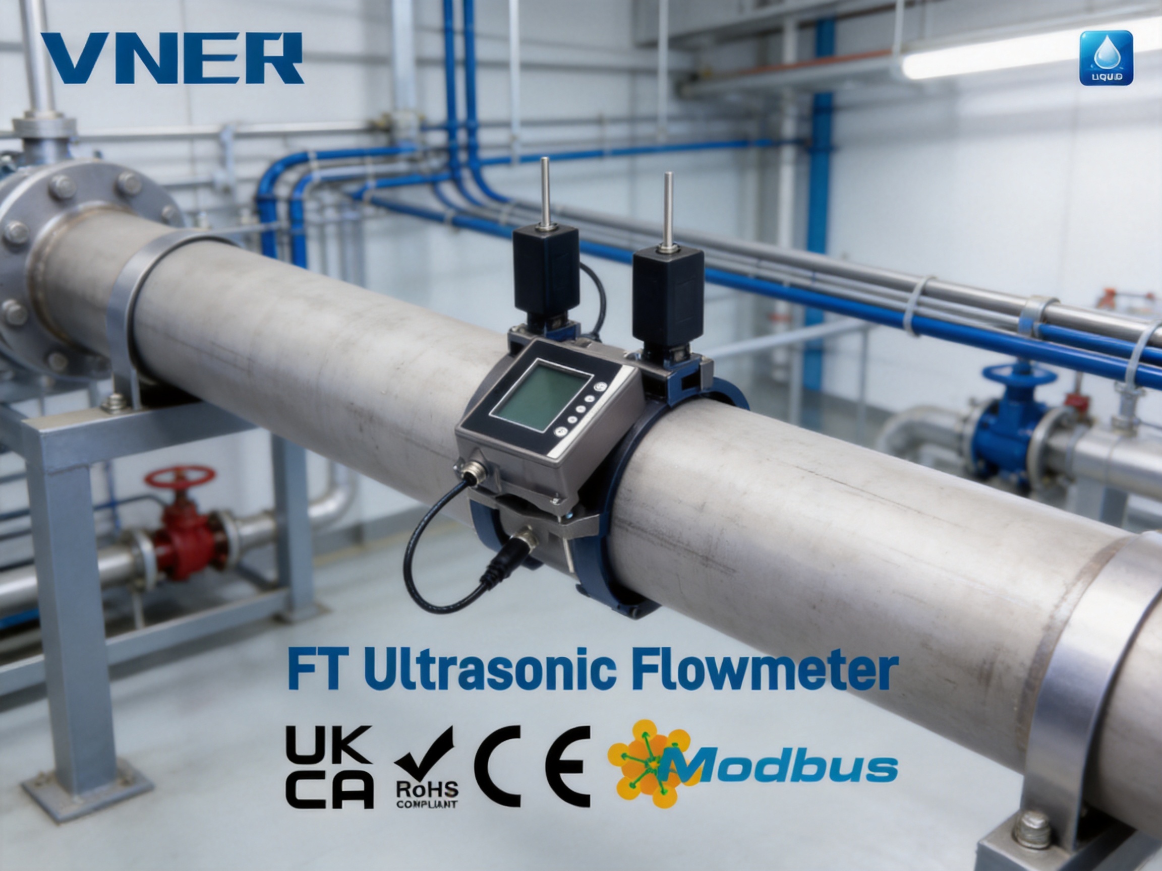
6. Applications Across Industrial and Building Systems
The VNFT211 is suitable for clean water and compatible single-phase liquids in a wide range of installations. Its strongest application areas are systems where non-intrusive measurement, small pipe capability, and rapid deployment are important.
6.1 Water Supply and Distribution
Water supply systems often contain numerous small branch lines. Installing an inline meter on every branch can be expensive and may require changes to the existing network. A clamp-on meter allows operators to measure branch flow, verify distribution, identify abnormal consumption, and compare the performance of different sections without rebuilding the pipeline.
Applications include building water systems, utility distribution, equipment cooling water, process water branches, and local water balance studies. The instrument can also support leak investigation by comparing expected and measured flow at selected points.
6.2 HVAC Chilled Water Systems
HVAC systems depend on proper water flow through chillers, heat exchangers, air handling units, fan coil circuits, and distribution branches. Low flow can reduce heat transfer and cause inefficient operation, while excessive flow may increase pumping energy.
The VNFT211 can be used to check chilled-water flow without cutting into the piping. Its optional energy measurement configuration allows the system to function as an ultrasonic cooling or heating energy meter when appropriate temperature measurement and application configuration are provided. This supports energy consumption monitoring, system balancing, and cost allocation.
6.3 Heating Circuits
Heating-water networks can also benefit from external flow measurement. Operators can verify circulation through heat exchangers, monitor branch performance, and investigate uneven heating. The liquid temperature range up to 115 °C covers many hot-water applications, subject to proper sensor installation and environmental conditions.
6.4 Equipment Skids and Packaged Systems
Packaged equipment often has limited space and compact pipe layouts. Modifying these systems to install an inline meter may affect the skid design or require extensive rework. A clamp-on meter can be added after fabrication, making it useful for commissioning, performance testing, and ongoing operation.
Examples include pump skids, filtration packages, water treatment systems, cooling modules, heat exchange units, and industrial utility packages. The small-pipe range is particularly relevant to these applications.
6.5 Laboratory and Pilot Installations
Laboratory and pilot systems frequently change configuration as testing progresses. Permanent inline meters may not be justified for every line, and process interruption can disrupt experiments. The VNFT211 can provide temporary or semi-permanent measurement while preserving the original piping arrangement.
6.6 Temporary Verification and Performance Audits
Portable or quickly installed flow measurement is valuable during commissioning and troubleshooting. Engineers may need to compare a control system reading with an independent measurement, verify a pump operating point, investigate a suspected blockage, or assess the performance of a heat exchanger.
Because the VNFT211 can be installed without permanent pipe modification, it can support temporary verification campaigns. After the survey, the instrument can be moved to another measuring point or retained at the location for continued monitoring.
6.7 Automation and Control System Integration
Industrial facilities increasingly require flow data to be available in central control systems. The VNFT211’s 4–20 mA signal is compatible with conventional analog input modules, while Modbus RS485 supports digital data exchange. This enables flow information to be included in process displays, historical trends, alarm logic, energy reports, and maintenance systems.
The optional relay output can be used for local alarm functions, and the pulse output can support totalized flow counting or connection to compatible monitoring equipment. These communication capabilities make the product appropriate for both stand-alone field measurement and integrated automation architectures.
7. Optional Thermal Energy Measurement
In addition to flow measurement, the VNFT211 can be configured as an ultrasonic cooling or heating energy meter. Thermal energy calculations generally combine flow measurement with the temperature difference between supply and return lines. In a chilled-water system, the calculated energy indicates cooling consumption. In a heating system, it indicates delivered thermal energy.
This capability can support building energy management, HVAC optimization, tenant cost allocation, and equipment performance analysis. It allows users to evaluate not only how much water is moving, but also how much useful thermal energy is being transferred.
7.1 Benefits for Energy Management
- Monitoring chiller inlet and outlet flow conditions.
- Comparing energy use between building zones or equipment branches.
- Identifying low-flow conditions that reduce heat transfer.
- Supporting maintenance decisions through trend analysis.
- Improving the accuracy of energy allocation between users or departments.
- Evaluating the effect of control adjustments and system balancing.
The energy-meter configuration is especially attractive for retrofit projects because it avoids extensive pipeline work. Existing HVAC circuits can be assessed without removing pipe sections or interrupting building services.
8. Product Reliability and Protection Features
Industrial instruments must operate in environments that include vibration, electrical disturbances, temperature changes, dust, and occasional handling stress. The VNFT211 incorporates several features intended to support stable field operation.
8.1 IP65 Enclosure
The IP65 enclosure rating provides protection against dust ingress and water jets from limited directions. This is appropriate for many indoor industrial areas, plant rooms, utility spaces, and protected outdoor installations. The final installation should still consider direct exposure, condensation, chemical vapors, and local enclosure requirements.
8.2 Electrical Protection
Power reverse connection protection helps reduce the risk of damage caused by incorrect DC wiring. Surge and short-circuit protection provide additional safeguards against common electrical faults. These protections are important when the meter is installed in shared industrial control panels or supplied from field wiring that may be subject to transient disturbances.
8.3 Mechanical Resistance
The product is specified for vibration from 10 to 55 Hz with a displacement of 1.5 mm. It also has a shock resistance specification of 100 m/s² for 16 ms. These characteristics support use in practical industrial environments, although severe vibration sources should still be assessed before installation.
8.4 Environmental Materials
The housing combines aluminum and industrial-grade plastics. This construction balances mechanical strength, weight, insulation, and manufacturing flexibility. Proper material selection contributes to enclosure durability and supports consistent production across different product configurations.
9. Manufacturing and Engineering Strengths
The performance of an industrial flow meter depends not only on its design but also on how consistently it is manufactured, tested, calibrated, and supported. Jiangsu Vner Electronic Technology Co., Ltd. is a specialized industrial flow meter manufacturer based in Yangzhou, China. Since 2011, the company has developed solutions covering electromagnetic, Coriolis, vortex, swirl, turbine, thermal mass, ultrasonic, and metal tube rotameter technologies.
This broad product portfolio provides an important engineering advantage. A customer’s process may include water, gas, steam-related utility systems, corrosive liquids, slurry, or clean single-phase fluids. A manufacturer with experience across several measurement principles can evaluate the application more objectively and recommend a technology based on process conditions rather than forcing every project toward one product type.
9.1 Engineering-Driven Product Selection
Flow meter selection requires more than knowing the pipe diameter. Engineers must consider liquid composition, conductivity, temperature, pressure, viscosity, solids content, flow range, pipe material, installation restrictions, required outputs, and accuracy expectations.
The company’s experience with multiple flow technologies supports application-based sizing and selection. For example, a clamp-on ultrasonic meter may be ideal for a clean liquid retrofit, while another process may require an electromagnetic meter, Coriolis meter, thermal mass meter, or turbine design. This broader understanding helps prevent unsuitable technology choices and improves the probability of long-term field success.
9.2 Manufacturing Capacity
The company operates modern facilities across three plants with a total area of approximately 23,000 square meters. Its technical team includes more than 150 personnel, supporting product development, production, quality, calibration, engineering, and customer service activities.
A substantial manufacturing base can provide several benefits:
- Better control of component sourcing and assembly processes.
- Dedicated space for production, testing, and calibration.
- Improved traceability of instruments and key components.
- Greater flexibility for standard and customized configurations.
- More efficient support for project-based and OEM requirements.
- Capacity to manage multiple flow meter technologies in parallel.
9.3 In-House Calibration
Calibration is central to flow meter quality. A product may have a sound theoretical design, but its practical performance depends on sensor matching, electronics verification, parameter accuracy, and final test procedures. In-house calibration allows the manufacturer to verify performance before shipment and to maintain greater control over product consistency.
For the VNFT211, calibration and verification can support the stated accuracy of ±2%, with performance up to ±1% after calibration under suitable conditions. Actual results depend on pipe condition, liquid properties, installation quality, and application parameters, but controlled factory testing establishes a stronger baseline for field commissioning.
9.4 Quality Process and Traceability
Industrial customers increasingly require documentation, repeatability, and traceability. Quality processes should cover incoming components, assembly steps, wiring, software or parameter configuration, enclosure inspection, output verification, and final testing.
Traceability is especially important for EPC projects, OEM systems, and facilities where instruments must be replaced or audited over many years. Consistent records help identify the product configuration, testing status, and application information associated with each meter.
9.5 Automation and Product Consistency
Increasingly automated manufacturing can reduce variation in repetitive assembly tasks and improve production efficiency. Automation does not replace engineering judgment, but it can make critical manufacturing steps more repeatable. When combined with inspection and calibration, it supports stable product quality across production batches.
For customers purchasing multiple instruments for the same facility, consistency is valuable. Similar meters should respond similarly, use compatible communication structures, and follow the same configuration logic. This reduces commissioning time and simplifies maintenance training.
9.6 International Project Experience
The company has delivered more than 2,000 engineering projects in over 30 countries. This experience exposes the manufacturer to different standards, climate conditions, process industries, documentation requirements, and system integration practices.
Its customers and project partners include EPC contractors, industrial end users, and OEM organizations in sectors such as oil and gas, petrochemical, polysilicon, power, water, and wastewater. Although the VNFT211 is designed primarily for water and compatible single-phase liquids, experience in demanding industrial sectors supports a practical understanding of installation, reliability, documentation, and project coordination.
10. Comparing the VNFT211 with Other Flow Meter Technologies
No single flow meter technology is ideal for every application. The correct comparison should consider process compatibility, installation requirements, accuracy, maintenance, pressure loss, and total cost of ownership.
10.1 Comparison with Inline Turbine Meters
Turbine meters can provide good repeatability for clean liquids but contain an internal rotor. They require direct installation into the pipe and may be sensitive to wear, contamination, and flow disturbances. The VNFT211 has no internal moving parts and can be installed externally, making it more attractive for retrofit measurement and applications where pressure loss or maintenance access is a concern.
10.2 Comparison with Electromagnetic Flow Meters
Electromagnetic flow meters are widely used for conductive liquids and can provide excellent accuracy. However, they require direct pipe installation and typically need a suitable liner and electrodes in contact with the liquid. The VNFT211 avoids wetted components and is more flexible for temporary measurement, clean water retrofit work, and systems where pipe modification is not acceptable.
10.3 Comparison with Coriolis Flow Meters
Coriolis meters can measure mass flow and often provide high accuracy, but they are generally more expensive, heavier, and more demanding to install than a small clamp-on ultrasonic meter. For applications that require volumetric flow of water rather than direct mass flow, the VNFT211 can provide a more economical and less intrusive solution.
10.4 Comparison with Differential Pressure Meters
Orifice plates and other differential pressure devices can be robust, but they create permanent pressure loss and require impulse connections, transmitters, and carefully designed installation arrangements. A clamp-on ultrasonic meter does not require a restriction in the pipe, which may reduce energy loss and simplify retrofit projects.
10.5 Comparison with Insertion Meters
Insertion meters may reduce the need to remove an entire pipe section, but they still require a penetration, fitting, or hot-tap arrangement. The VNFT211 requires no penetration into the pipe. This is a major advantage when the pipeline must remain sealed or when the customer wants to avoid pressure-boundary modifications.
11. Digital Communication and Control Integration
Modern flow measurement is increasingly connected to automation and data systems. A local display is useful for operators, but plants also require historical trends, remote alarms, performance calculations, and centralized reporting.
The standard 4–20 mA output provides a familiar and robust method for transmitting flow information to a PLC, DCS, recorder, controller, or building management system. The current signal is suitable for long cable runs when correctly installed and isolated according to the control system design.
Modbus RS485 provides a digital communication path for integrating the meter with supervisory systems. Depending on system configuration, the communication link can support access to flow values, accumulated flow, status information, alarm data, and configuration-related parameters.
The optional pulse output can be used for totalized volume measurement, while the relay output can support threshold alarms. For example, a relay can be assigned to a high-flow, low-flow, or instrument-status condition, subject to the selected configuration.
11.1 Typical Integration Architecture
A typical installation may include the VNFT211 at the pipeline, a 24 VDC instrument supply, a 4–20 mA connection to a PLC analog input, and an RS485 connection to a supervisory network. The local LCD provides field verification, while the control room receives data for monitoring and analysis.
This arrangement allows operators to compare local and remote values during commissioning. It also supports faster troubleshooting because technicians can examine the instrument display without relying entirely on the central system.
12. Maintenance and Lifecycle Benefits
The clamp-on design reduces many routine maintenance tasks associated with wetted or moving components. There is no internal rotor to inspect, no electrode surface inside the pipe, and no pressure-bearing meter body to remove for routine sensor servicing.
Maintenance should focus on ensuring that the transducers remain firmly positioned, the coupling remains effective, the cable connections are secure, and the pipe surface has not deteriorated beneath the sensors. In environments with vibration, periodic inspection can confirm that the sensor spacing and clamp tension remain stable.
The instrument’s data backup, protected enclosure, and low power consumption also support long-term operation. If the meter is used temporarily, it can be removed and redeployed at another point without leaving a permanent modification in the pipeline.
12.1 Recommended Maintenance Checks
- Inspect the transducer clamps and mounting position.
- Check for loose wiring, damaged cables, or moisture ingress.
- Confirm that the pipe surface remains suitable for acoustic coupling.
- Review the displayed signal and flow status.
- Compare local readings with the control system value.
- Verify that the application parameters remain correct.
- Check the low-flow cutoff and response-time settings.
- Review alarms and accumulated flow data.
13. Selection Guidance for Engineers and Buyers
Before ordering a VNFT211, users should prepare the basic information needed to confirm suitability. This improves quotation accuracy, reduces commissioning time, and helps ensure that the selected transducer arrangement matches the pipeline.
13.1 Information to Confirm
- Nominal pipe size and actual outside diameter.
- Pipe material, such as carbon steel, stainless steel, PVC, PP, or PVDF.
- Pipe wall thickness and any internal lining.
- Liquid type and whether it is single-phase.
- Normal, minimum, and maximum flow rate.
- Liquid temperature range.
- Whether the pipe remains full during operation.
- Available straight-pipe length.
- Required outputs and communication protocol.
- Whether energy measurement is required.
- Ambient temperature, humidity, and vibration conditions.
The product is not intended for every liquid or every pipe condition. Liquids with large quantities of solids, entrained gas, or unstable phase conditions may require another measurement method. Application review is therefore an important part of responsible instrument selection.
14. Questions and Answers
Q1. What is the main advantage of the VNFT211?
The main advantage is non-intrusive measurement. The ultrasonic transducers are installed on the outside of the pipe, so the pipeline does not need to be cut and the process does not normally need to be stopped. The meter also avoids permanent pressure loss and direct contact with the liquid.
Q2. What pipe sizes can the VNFT211 measure?
The specified pipe size range is DN15 to DN65. This makes the model particularly suitable for small-diameter pipelines, branch lines, equipment skids, building services, laboratory systems, and compact utility networks.
Q3. Can the meter be used on plastic pipes?
Yes. The VNFT211 is compatible with rigid plastic pipes including PVC, PP, and PVDF, as well as metal pipes. The pipe must provide a suitable acoustic path and remain within the specified application conditions.
Q4. Does the meter contact the liquid?
No. The transducers are clamped onto the external pipe surface. This eliminates wetted sensor components and helps reduce contamination risk.
Q5. What liquids are suitable?
The product is intended for water and other single-phase liquids without solid particles or impurities. Liquids containing substantial solids, gas pockets, or unstable phases may reduce ultrasonic signal quality and should be reviewed before selection.
Q6. What is the accuracy?
The stated accuracy is ±2%, with performance up to ±1% after calibration under suitable conditions. Actual field performance depends on pipe condition, transducer installation, liquid properties, application parameters, and flow profile.
Q7. What outputs are available?
Standard outputs include 4–20 mA and Modbus RS485. Optional functions include pulse output using OCT and relay alarm output.
Q8. Can it be connected to a PLC or DCS?
Yes. The 4–20 mA output can connect to analog input modules, and Modbus RS485 can be used for digital communication with PLC, DCS, supervisory, and data acquisition systems.
Q9. Can it measure heating and cooling energy?
Yes. The instrument can be configured as an ultrasonic cooling or heating energy meter for suitable HVAC and thermal-water applications. Energy measurement combines flow information with temperature-related inputs and application configuration.
Q10. What is the operating temperature range?
The liquid temperature range is 0 to 115 °C, provided there is no surface freezing. The ambient temperature range is –10 to 60 °C.
Q11. Does the meter create pressure loss?
No permanent pressure loss is introduced by the measurement principle because the transducers are mounted outside the pipe and do not obstruct the flow path.
Q12. Is the meter suitable for temporary testing?
Yes. Its quick external installation makes it suitable for commissioning, comparative testing, flow verification, troubleshooting, and short-term performance audits.
Q13. What should be done if the signal is unstable?
Check the pipe surface, acoustic coupling, sensor spacing, pipe parameters, liquid condition, and installation location. Air bubbles, suspended solids, an empty or partially filled pipe, excessive vibration, and nearby flow disturbances may affect the signal.
Q14. Why is the low-velocity cutoff useful?
The factory cutoff of 0.08 m/s helps prevent false flow indications caused by very small fluctuations when the actual flow is close to zero. Applications with extremely low flow should be reviewed carefully during commissioning.
Q15. What manufacturing support is available?
Jiangsu Vner Electronic Technology Co., Ltd. provides flow measurement products supported by engineering selection, in-house calibration, quality processes, traceability, and experience in industrial and international projects. The company also manufactures multiple flow meter technologies for different liquid, gas, and slurry applications.
15. Conclusion
The VNFT211 clamp-on ultrasonic flow meter is a practical solution for small-pipe liquid measurement where conventional inline installation is costly, disruptive, or impossible. Its transit-time ultrasonic principle enables measurement from outside the pipe, avoiding pipe cutting, process interruption, pressure loss, and direct contact with the liquid.
With support for DN15–DN65 pipelines, metal and rigid plastic pipes, 4–20 mA output, Modbus RS485 communication, optional pulse and relay functions, a high-resolution LCD, adjustable response time, low power consumption, and optional thermal energy measurement, the instrument is suited to both stand-alone field use and integrated automation systems.
Its advantages are especially clear in retrofit projects, HVAC circuits, water distribution branches, equipment skids, laboratory systems, temporary verification work, and industrial process-water applications. The product’s value extends beyond its compact hardware. Careful application selection, external installation, factory calibration, product protection, and manufacturing consistency all contribute to dependable long-term measurement.
Supported by Jiangsu Vner Electronic Technology Co., Ltd.’s broad flow measurement portfolio, modern manufacturing facilities, in-house calibration, technical team, and international project experience, the VNFT211 represents an engineering-focused approach to non-intrusive flow measurement. For users seeking reliable flow information without redesigning an existing pipeline, it offers an efficient balance of installation flexibility, operating convenience, system integration, and lifecycle value.
References
1. Product technical information for the VNFT211 Clamp-On Ultrasonic Flow Meter, including operating principle, specifications, outputs, protection functions, and application guidance.
2. General principles of transit-time ultrasonic flow measurement for single-phase liquids.
3. Industrial instrumentation practices for flow meter installation, commissioning, calibration, and signal verification.
4. HVAC chilled-water and heating-water measurement practices for flow monitoring and thermal energy management.
5. Industrial automation practices for 4–20 mA, pulse, relay, and Modbus RS485 instrument integration.
6. Manufacturer information concerning Jiangsu Vner Electronic Technology Co., Ltd., its flow measurement product range, manufacturing facilities, technical team, calibration capabilities, and project experience.
Product: VNFT Clamp-On Ultrasonic Flow Meter



Products
Contact Information
-

+86 18652789521
+86-0514-83633600 / 83633900 -

+86-0514-83633600 / 83633900
-

s@vner.com.cn
katherine@vner.com.cn -

No. 11 Xingye Road, Chenji Town Industrial Park, Yizheng, Yangzhou, China
